24 Shaders
Difficulty Very hard
Introduction
This lesson is probably the most anticipated one. We already talked about shaders, and that is the most demanding topic.
The funny thing is that we have been using them since the beginning. When we are creating Three.js built-in materials, those materials are composed of shaders. Everything sowing up on the WebGL render is made possible because of shaders, but it’s time to create them on our own.
We will start by explaining what shaders are and when to use them. Then we will create our own very simple shaders. We will, of course, cover the syntax of the shader language. And finally, we will do some exercises to practice classic situations.
What is a shader
A shader is, in fact, one of the main components of WebGL. If we had started WebGL without Three.js, it would have been one of the first things we would have to learn, and this is why native WebGL is so hard.
A shader is a program written in GLSL that is sent to the GPU. They are used to position each vertex of a geometry and to colorize each visible pixel of that geometry . The term “pixel” isn’t accurate because each point in the render doesn’t necessarily match each pixel of the screen and this is why we prefer to use the term “fragment” so don’t be surprised if you see both terms.
Then we send a lot of data to the shader such as the vertices coordinates, the mesh transformation, information about the camera and its field of view, parameters like the color, the textures, the lights, the fog, etc. The GPU then processes all of this data following the shader instructions, and our geometry appears in the render.
There are two types of shaders, and we need both of them.
Vertex shader
The vertex shader’s purpose is to position the vertices of the geometry. The idea is to send the vertices positions, the mesh transformations (like its position, rotation, and scale), the camera information (like its position, rotation, and field of view). Then, the GPU will follow the instructions in the vertex shader to process all of this information in order to project the vertices on a 2D space that will become our render —in other words, our canvas.
When using a vertex shader, its code will be applied on every vertex of the geometry. But some data like the vertex position will change between each vertex. This type of data —the one that changes between vertices— is called an attribute . But some data doesn’t need to switch between each vertex like the position of the mesh. Yes, the location of the mesh will impact all the vertices, but in the same way. This type of data —the one that doesn’t change between vertices— is called a uniform . We will get back to attributes and uniforms later.
The vertex shader happens first. Once the vertices are placed, the GPU knows what pixels of the geometry are visible and can proceed to the fragment shader.
Fragment shader
The fragment shader purpose is to color each visible fragment of the geometry.
The same fragment shader will be used for every visible fragment of the geometry. We can send data to it like a color by using uniforms —just like the vertex shader, or we can send data from the vertex shader to the fragment shader. We call this type of data —the one that comes from the vertex shader to the fragment shader— varying . We will get back to this later.
The most straightforward instruction in a fragment shader can be to color all the fragments with the same color. We get the equivalent of the MeshBasicMaterial —if we had set only the color property.
Or we can send more data to the shader, for instance, a light position. We can then color the fragments according to how much the face is in front of the light source. We would get the MeshPhongMaterial equivalent—if we had one light in the scene.
Summary
The vertex shader position the vertices on the render.
The fragment shader color each visible fragment (or pixel) of that geometry.
The fragment shader is executed after the vertex shader .
Data that changes between each vertices (like their position) is called attribute and can only be used in the vertex shader .
Data that doesn’t change between vertices (like the mesh position or a color) is called uniform and can be use in both the vertex shader and the fragment shader .
We can send data from the vertex shader to the fragment shader using varying .
Why writing our own shaders
Three.js materials try to cover as many situations as possible, but they have limitations. If we want to break those limits, we have to write our own shaders.
It can also be for performance reasons. Materials like MeshStandardMaterial are very elaborate and involve a lot of code and calculations. If we write our own shader, we can keep the features and calculations to the minimum. We have more control over the performance.
Writing our own shader is also an excellent way to add post-process to our render, but we will see this in a dedicated lesson.
Once you master the shaders, they’ll become a must in all your projects.
Create our first shaders with RawShaderMaterial
To create our first shader, we need to create a particular material. This material can be a ShaderMaterial or a RawShaderMaterial. The difference between these two is that the ShaderMaterial will have some code automatically added to the shader codes while the RawShaderMaterial, as its name suggests, will have nothing.
We will start with the RawShaderMaterial to better understand what’s happening.
The starter contains a simple plane with a MeshBasicMaterial on it.
Replace that MeshBasicMaterial with a RawShaderMaterial:
const material = new THREE.RawShaderMaterial()
JavaScript
Copy
You should get an error.
As we said earlier, we need to provide both the vertex and the fragment shader. You can do this with the vertexShader and fragmentShader properties:
const material = new THREE.RawShaderMaterial({
    vertexShader: '',
    fragmentShader: ''
})
JavaScript
Copy
The problem with that technique is that simple quotes can contain only one line inside —double-quotes too. Our shaders —as simple as they are at the start, will be too long to be written on one line.
A reliable solution is to use back quotes —also called backtick, acute or left quote. Most modern browsers support them. This technique is called template literals, and we can use line breaks in it.
The key or shortcut to write this character depends on your keyboard. Here’s a thread on the subject to help you: https://superuser.com/questions/254076/how-do-i-type-the-tick-and-backtick-characters-on-windows/879277
Once you’ve found the key, change your simple quotes with back quotes:
const material = new THREE.RawShaderMaterial({
    vertexShader: ``,
    fragmentShader: ``
})
JavaScript
Copy
We can finally write our shaders. Just copy the code, we will explain everything later:
const material = new THREE.RawShaderMaterial({
    vertexShader: `
        uniform mat4 projectionMatrix;
        uniform mat4 viewMatrix;
        uniform mat4 modelMatrix;

        attribute vec3 position;

        void main()
        {
            gl_Position = projectionMatrix * viewMatrix * modelMatrix * vec4(position, 1.0);
        }
    `,
    fragmentShader: `
        precision mediump float;

        void main()
        {
            gl_FragColor = vec4(1.0, 0.0, 0.0, 1.0);
        }
    `
})
JavaScript
Copy
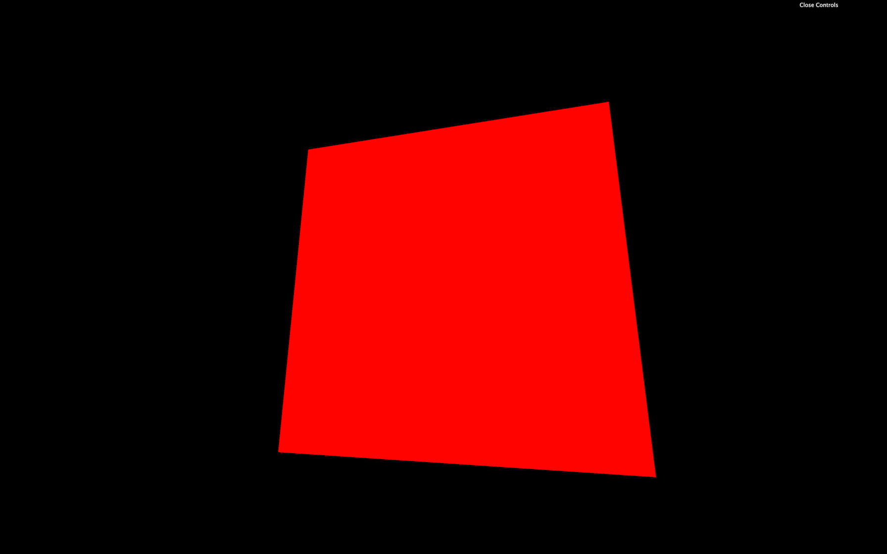
You should get a red plane. Congratulations, you might not yet understand what’s written here, but it’s your first shader and a good start for an incredible journey.
Separate the shaders in different files
Before we get into the code itself, let’s try to improve the way we work. The back quotes are an excellent solution for small code, and we will use it in future lessons with shaders, but we are missing syntax coloration. Once we have multiple shaders with a lot of code in it, our script will become unbearable. Having a good and comfortable setup is essential.
Shader files
We are going to move the code into separate files. First, move the vertex shader code and the fragment shader codes respectively in /src/shaders/test/vertex.glsl and /src/shaders/test/fragment.glsl .
Even if we will have only one shader in our project, it’s a healthy habit to separate and organize our code as best as possible. Consequential projects can have dozens of custom shaders.
Unless your code editor already supports glsl, the syntax coloration probably doesn’t work for those two new files. To add the syntax coloration, if you are using VSCode, go to your plugins, search for shader , and install the Shader languages support for VS Code plugin. If you are using another code editor, look for compatible plugins and keep an eye on the popularity and the reviews.
Once installed, you should have a nice syntax coloration on the .glsl files. If not, try to restart your code editor.
Syntax coloration is cool, but having a linter is even better. A linter will validate your code and find potential errors while you are writing it. It can be really useful to avoid basic mistakes without having to test the result on the browser.
We won’t use one in the following lessons because installing it can be hard but if you want to give it a try, I recommend you watching this video in the Lewis Lepton Youtube Channel: https://www.youtube.com/watch?v=NQ-g6v7GtoI
The linter will also produce errors on incomplete shaders which is a problem because we are going to write partial shaders a little later in the lesson. It’s up to you, but you can give it a try.
Import
Let’s try to import the files into our script:
import testVertexShader from './shaders/test/vertex.glsl'
import testFragmentShader from './shaders/test/fragment.glsl'
JavaScript
Copy
Unfortunately, we get a Webpack error. We need to tell Webpack how to handle .glsl files.
To do this, go to the /bundler/webpack.common.js where loaders are set in the rules array property.
Add the following rule at the rules —or anywhere, as long as it’s in the array —and don’t forget the comma between those rules :
module.exports = {
    // ...

    module:
    {
        rules:
        [
            // ...

            // Shaders
            {
                test: /\.(glsl|vs|fs|vert|frag)$/,
                exclude: /node_modules/,
                use: [
                    'raw-loader'
                ]
            }
        ]
    }
}
JavaScript
Copy
This rule solely tells Webpack to provide the raw content of the files having .glsl , .vs , .fs , .vert or .frag as extension. We might as well have used .glsl , but some people feel more comfortable using other file extensions.
Re-launch the server with npm run dev and the Webpack error will disappear.
If you log testVertexShader and testFragmentShader , you’ll get the shader code as a plain string. We can use these two variables in our RawShaderMaterial:
const material = new THREE.RawShaderMaterial({
    vertexShader: testVertexShader,
    fragmentShader: testFragmentShader
})
JavaScript
Copy
Properties
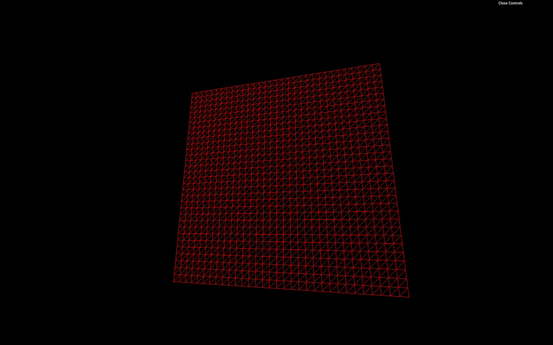
Most of the common properties we’ve covered with other materials such as wireframe , side , transparent or flatShading are still available for the RawShaderMaterial:
const material = new THREE.RawShaderMaterial({
    vertexShader: testVertexShader,
    fragmentShader: testFragmentShader,
    wireframe: true
})
JavaScript
Copy
But properties like map , alphaMap , opacity , color , etc. won’t work anymore because we need to write these features in the shaders ourselves.
Comment or delete the wireframe line.
GLSL
The language used to code the shaders is called GLSL and stands for OpenGL Shading Language. It’s close to C language. Let’s learn the basics of its syntax.
Logging
There is no console and, thus, no way to log values. That is due to the code being executed for every vertex and every fragment. It would make no sense to log one value.
Indentation
The indentation is not essential. You can indent as you like.
Semicolon
The semicolon is required to end any instruction. Forgetting even one semicolon will probably result in a compilation error, and the whole material won’t work.
Variables
It’s a typed language, meaning that we must specify a variable’s type, and we cannot assign any other type to that variable.
To declare a variable, we must start by the type, followed by the name (usually in camelCase), then the = sign, then the value, and end with a ; :
float fooBar = 0.123;
GLSL
Copy
There are multiple different types.
Float
Floats are decimals. They can be negative or positive. We must always provide the . of the decimals even if the value is rounded:
float foo = - 0.123;
float bar = 1.0;
GLSL
Copy
We can do mathematic operations like + , - , * and / :
float a = 1.0;
float b = 2.0;
float c = a / b;
GLSL
Copy
Integer
Integers work just like the floats, but without the decimals’ . :
int foo = 123;
int bar = - 1;
GLSL
Copy
We can also do mathematic operations:
int a = 1;
int b = 2;
int c = a * b;
GLSL
Copy
But we can’t mix float and int in these operations:
float a = 1.0;
int b = 2;
float c = a * b;
GLSL
Copy
But we can convert types on the fly:
float a = 1.0;
int b = 2;
float c = a * float(b);
GLSL
Copy
Boolean
Booleans are just booleans:
bool foo = true;
bool bar = false;
GLSL
Copy
Vector 2
This is where things get interesting. If we want to store values like 2 coordinates with x and y properties, we can use a vec2 :
vec2 foo = vec2(1.0, 2.0);
GLSL
Copy
An empty vec2 will result in an error:
vec2 foo = vec2();
GLSL
Copy
We can change these properties after creating the vec2 :
vec2 foo = vec2(0.0  );
foo.x = 1.0;
foo.y = 2.0;
GLSL
Copy
Doing operations like multiplying a vec2 with a float will operate both the x and the y properties:
vec2 foo = vec2(1.0, 2.0);
foo *= 2.0;
GLSL
Copy
Vector 3
vec3 is just like vec2 , but with a third property named z . It’s very convenient when one needs 3D coordinates:
vec3 foo = vec3(0.0);
vec3 bar = vec3(1.0, 2.0, 3.0);
bar.z = 4.0;
GLSL
Copy
While we can use x , y , and z , we can also work with r , g , and b . This is just syntax sugar and the result is exactly the same. It’s very effective when we use a vec3 to store colors:
vec3 purpleColor = vec3(0.0);
purpleColor.r = 0.5;
purpleColor.b = 1.0;
GLSL
Copy
A vec3 can also be partially created from a vec2 :
vec2 foo = vec2(1.0, 2.0);
vec3 bar = vec3(foo, 3.0);
GLSL
Copy
We can also take a part of the vec3 to generate a vec2 :
vec3 foo = vec3(1.0, 2.0, 3.0);
vec2 bar = foo.xy;
GLSL
Copy
Here, the bar will be a vec2 with 1.0 , and 2.0 as values.
This is called a swizzle and we can also use the properties in a different order:
vec3 foo = vec3(1.0, 2.0, 3.0);
vec2 bar = foo.yx;
GLSL
Copy
Vector 4
Finally, the vec4 works like it’s two predecessors but with a fourth value named w or a — w because there is no letter after z in the alphabet and a for “alpha”:
vec4 foo = vec4(1.0, 2.0, 3.0, 4.0);
vec4 bar = vec4(foo.zw, vec2(5.0, 6.0));
GLSL
Copy
There are other types of variables such as mat2 , mat3 , mat4 , or sampler2D , but we will see those later.
Functions
Just like in most programming languages, we can create and use functions.
A function must start with the type of the value that will be returned:
float loremIpsum()
{
    float a = 1.0;
    float b = 2.0;

    return a + b;
}
GLSL
Copy
If the function isn’t supposed to return anything, we set the type to void :
void justDoingStuff()
{
    float a = 1.0;
    float b = 2.0;
}
GLSL
Copy
We can specify parameters, but we also have to provide their type:
float add(float a, float b)
{
    return a + b;
}
GLSL
Copy
This function is, as you can imagine, worthless.
Native function
GLSL has many built-in classic functions such as sin , cos , max , min , pow , exp , mod , clamp , but also very practical functions like cross , dot , mix , step , smoothstep , length , distance , reflect , refract , normalize .
Unluckily, there is no beginner-friendly documentation and, most of the time, we do naive searches on the web and usually end up on these three websites:
Shaderific documentation
https://www.shaderific.com/glsl-functions
Shaderific is an iOS application that lets you play with GLSL. The application is not something to care about, but the documentation isn’t too bad.
Kronos Group OpenGL reference pages
https://www.khronos.org/registry/OpenGL-Refpages/gl4/html/indexflat.php
This documentation deals with OpenGL, but most of the standard functions you’ll see will be compatible with WebGL. Let’s not forget that WebGL is just a JavaScript API to access OpenGL.
Book of shaders documentation
The book of shaders mainly focus on fragment shaders and has nothing to do with Three.js but it is a great resource to learn and it has its own glossary.
Understanding the vertex shader
Now that we know the GLSL syntax, let’s try to understand what’s in our shaders.
Keep in mind that the vertex shader purpose is to position each vertex of the geometry on the render 2D space. In other words, the vertex shader will convert the 3D vertices coordinates to our 2D canvas coordinates.
Main function
void main()
{
}
GLSL
Copy
This main function will be called automatically. As you can see, it doesn’t return anything ( void ).
gl_Position
The gl_Position variable already exists. We need to assign it. This variable will contain the position of the vertex on the screen. The goal of the instructions in the main function is to set this variable properly.
At the end of this instruction, we get a vec4 . This means that we can play with its x , y , z , and w properties directly on the gl_Position variable:
void main()
{
gl_Position = projectionMatrix * viewMatrix * modelMatrix * vec4(position, 1.0);
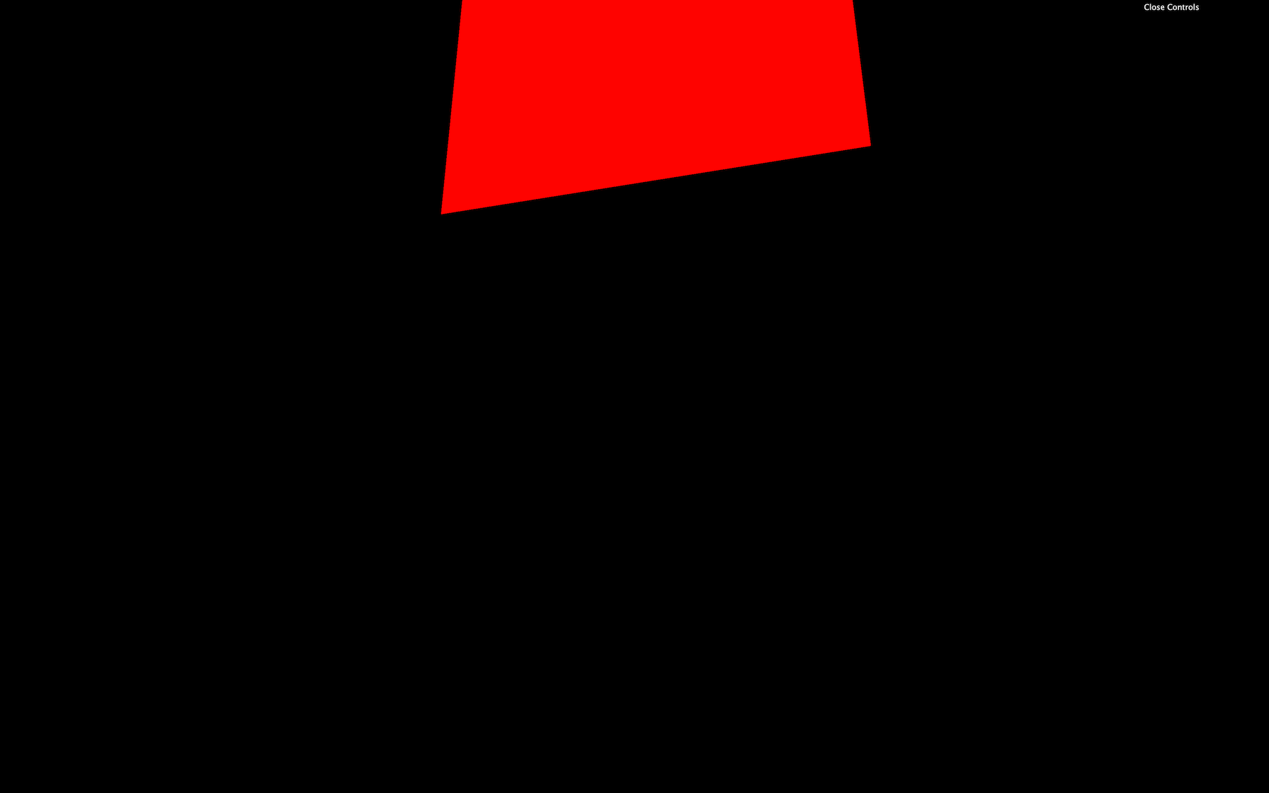
gl_Position.x += 0.5;
gl_Position.y += 0.5;
}
GLSL
Copy
The plane should move on the top right corner. But be careful; we didn’t truly move the plane in a 3D space as if we were playing with the position in Three.js. We did move the projected plane on a 2D space.
Think of it like a drawing you did on a paper. In this drawing, you have respected the perspective with vanishing points. Then, you move the whole picture to the top right corner of your desk. The perspective didn’t change inside the drawing.
You’re probably wondering why we need 4 values for the gl_Position if its final goal is to position vertices on a 2D space. It’s actually because of the coordinates or not precisely in 2D space; they are in what we call clip space which needs 4 dimensions.
A clip space is a space that goes in all 3 directions ( x , y , and z ) in a range from -1 to +1 . It’s like positioning everything in a 3D box. Anything out of this range will be “clipped” and disappear. The fourth value ( w ) is responsible for the perspective.
Fortunately, all of this is automatic, and, as a beginner, we don’t need to master everything. It’s just for the sake of knowing.
But what are we exactly sending to this gl_Position ?
Position attributes
First, we retrieve the vertex position with:
attribute vec3 position;
GLSL
Copy
Remember that the same code applies to every vertices of the geometry. Attributes are the only variable that will change between the vertices. The same vertex shader will be applied for each vertex and the position attribute will contain the x , y , and z coordinates of that specific vertex.
Then, we convert this vec3 to a vec4 :
gl_Position = /* ... */ vec4(position, 1.0);
GLSL
Copy
This is because the following matrices and the gl_Position need to use vec4 as we saw earlier.
Matrices uniforms
Each matrix will transform the position until we get the final clip space coordinates.
There are 3 matrices in our code, and because their values are the same for all the vertices of the geometry, we retrieve them by using uniforms .
uniform mat4 projectionMatrix;
uniform mat4 viewMatrix;
uniform mat4 modelMatrix;
GLSL
Copy
Each matrix will do a part of the transformation:
- The
modelMatrixwill apply all transformations relative to the Mesh. If we scale, rotate or move the Mesh, these transformations will be contained in themodelMatrixand applied to theposition. - The
viewMatrixwill apply transformations relative to the camera. If we rotate the camera to the left, the vertices should be on the right. If we move the camera in direction of the Mesh, the vertices should get bigger, etc. - The
projectionMatrixwill finally transform our coordinates into the final clip space coordinates.
If you want to find out more about those matrices and coordinates, here’s a good article: https://learnopengl.com/Getting-started/Coordinate-Systems.
To apply a matrix, we multiply it. If want to apply a mat4 to a variable, this variable has to be a vec4 . We can also multiply matrices with other matrices:
gl_Position = projectionMatrix * viewMatrix * modelMatrix * vec4(position, 1.0);
GLSL
Copy
There is actually a shorter version where the viewMatrix and the modelMatrix are combined into a modelViewMatrix :
uniform mat4 projectionMatrix;
uniform mat4 modelViewMatrix;

attribute vec3 position;

void main()
{
    gl_Position = projectionMatrix * modelViewMatrix * vec4(position, 1.0);
}
GLSL
Copy
This is shorter, but we have less control over each step.
We will actually make our code even longer to have a better understanding and more control on the position:
uniform mat4 projectionMatrix;
uniform mat4 viewMatrix;
uniform mat4 modelMatrix;

attribute vec3 position;

void main()
{
    vec4 modelPosition = modelMatrix * vec4(position, 1.0);
    vec4 viewPosition = viewMatrix * modelPosition;
    vec4 projectedPosition = projectionMatrix * viewPosition;

    gl_Position = projectedPosition;
}
GLSL
Copy
Those changes have the exact same result but we can now move the whole model just by tweaking the values of the modelPosition :
void main()
{
    vec4 modelPosition = modelMatrix * vec4(position, 1.0);
    modelPosition.y += 1.0;

    // ...
}
GLSL
Copy
The whole plane should appear higher.
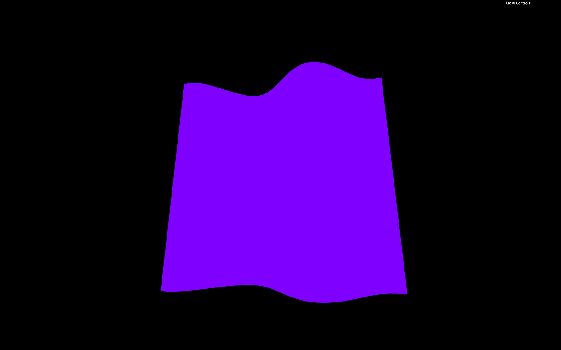
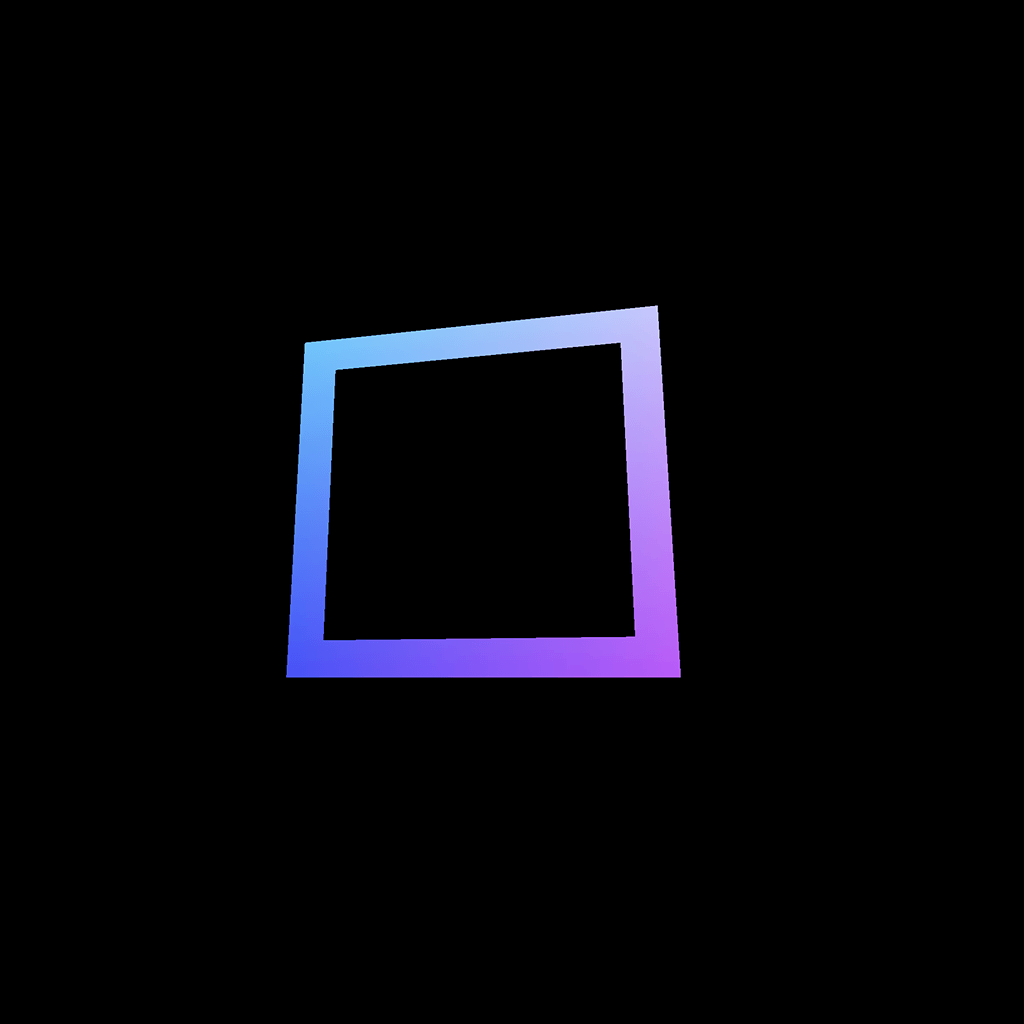
Or we can do cooler things such as transforming our plane wave:
void main()
{
    vec4 modelPosition = modelMatrix * vec4(position, 1.0);
    modelPosition.z += sin(modelPosition.x * 10.0) * 0.1;

    // ...
}
GLSL
Copy
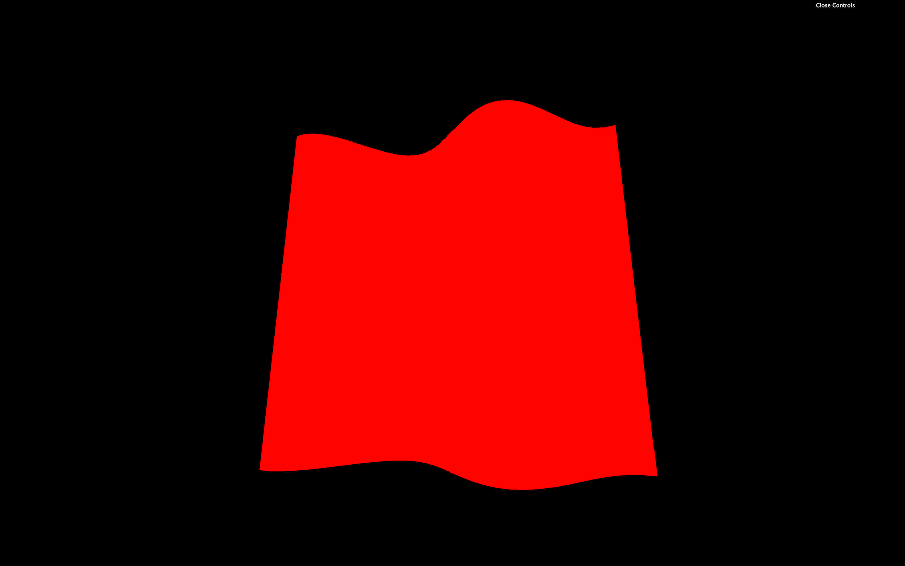
We changed the z by using the x coordinate through a sin(...) function. Good luck getting this result with Three.js built-in materials.
Understanding the fragment shader
The fragment shader code will be applied to every visible fragment of the geometry. That is why the fragment shader comes after the vertex shader.
The code is more manageable than the vertex shader.
Main function
Again, we face the main function:
void main()
{
}
GLSL
Copy
Precision
We also have an instruction at the top of the code:
precision mediump float;
GLSL
Copy
This instruction lets us decide how precise can a float be. There are different possible values:
highpmediumplowp
highp can have performance hit and might not even work on some devices. lowp can create bugs by the lack of precision. We ordinarily use mediump . We also could have set the precision for the vertex shader but it’s not required.
This part is automatically handled when we are using ShaderMaterial instead of RawShaderMaterial.
gl_FragColor
The gl_FragColor is like the gl_Position but for the color. It’s already declared, and we need to assign it in the main function.
It’s a vec4 with the first three values being the red, green, and blue channels ( r , g , b ) and the fourth value being the alpha ( a ):
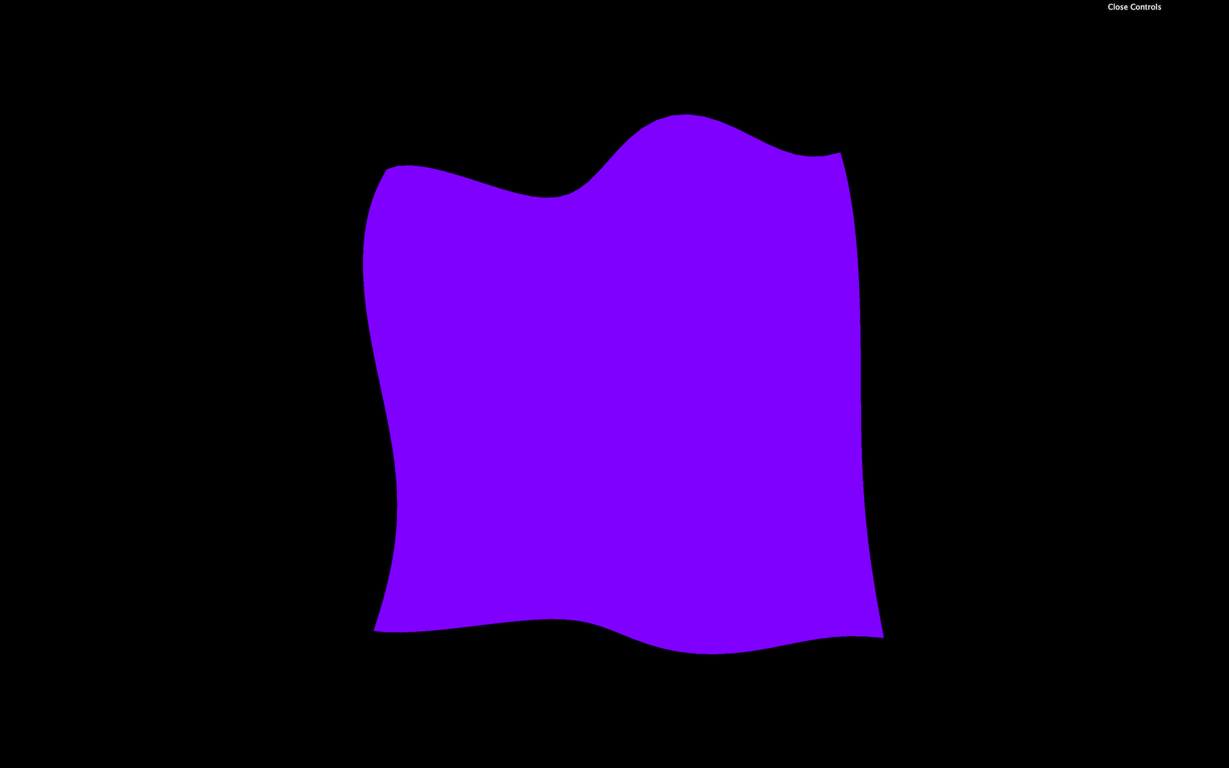
gl_FragColor = vec4(0.5, 0.0, 1.0, 1.0);
GLSL
Copy
This code will result on a purple color for the whole geometry.
Each property of gl_FragColor goes from 0.0 to 1.0 . We can go beyond those values with no error, but it won’t help us.
If we want to set an alpha below 1.0 , we also need to set the transparent property to true in the RawShaderMaterial:
const material = new THREE.RawShaderMaterial({
    vertexShader: testVertexShader,
    fragmentShader: testFragmentShader,
    transparent: true
})
JavaScript
Copy
Attributes
Attributes are values that change between each vertex. We already have one attribute named position that contains a vec3 of the coordinates of each vertex.
We can add our own attributes directly to the BufferGeometry as we did during the Geometries lesson.
We will add a random value for each vertex and move that vertex on the z axis according to that value for this lesson.
Let’s get back to the JavaScript and create a Float32Array of the right size right after creating the geometry . To know how much vertices we have in the geometry, we can use the already existing position attribute:
const count = geometry.attributes.position.count
const randoms = new Float32Array(count)
JavaScript
Copy
Then we fill this array with random values:
for(let i = 0; i < count; i++)
{
    randoms[i] = Math.random()
}
JavaScript
Copy
Finally, we use that array in a BufferAttribute and add it to our geometry attributes:
geometry.setAttribute('aRandom', new THREE.BufferAttribute(randoms, 1))
JavaScript
Copy
The first parameter of setAttribute(...) is the name of the attribute. That is the name we will use in the shader. We can choose any name but it’s good practice to prefix with a for “attribute”.
The first parameter of BufferAttribute is the data array and the second parameter is how many values compose one attribute. If we were to send a position, we would use 3 because positions are composed of 3 values ( x , y and z ). But here, it’s just 1 random value per vertex so we use 1 .
We can now retrieve this attribute in the vertex shader and use it to move the vertices:
// ...
attribute float aRandom;

void main()
{
    // ...
    modelPosition.z += aRandom * 0.1;

    // ...
}
GLSL
Copy
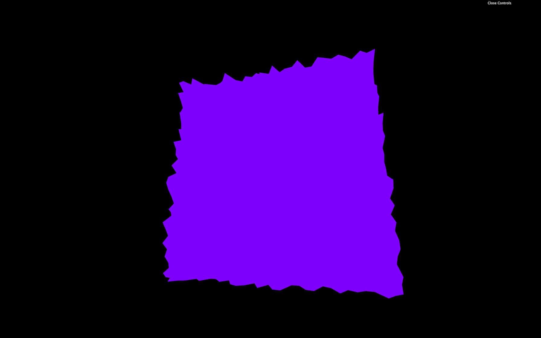
Now you get a plane composed of random spikes.
Varyings
We now want to color the fragments also with the aRandom attribute.
Unfortunately, we cannot use attributes directly in the fragment shader.
Fortunately, there is a way of sending data from the vertex shader to the fragment shader called varyings .
We have to do it on both the vertex and the fragment shader.
In the vertex shader, we need to create the varying before the main function. We will call our varying vRandom :
// ...

varying float vRandom;

void main()
{
    // ...
GLSL
Copy
You can call your varying as you want but I recommend prefixing with a v to distinguish them easily.
Then, we update the varying value in the main function:
varying float vRandom;

void main()
{
    // ...

    vRandom = aRandom;
}
GLSL
Copy
Finally, we get the varying value in the fragment shader with the same declaration, and we use it as we want in the main function:
precision mediump float;

varying float vRandom;

void main()
{
    gl_FragColor = vec4(0.5, vRandom, 1.0, 1.0);
}
GLSL
Copy
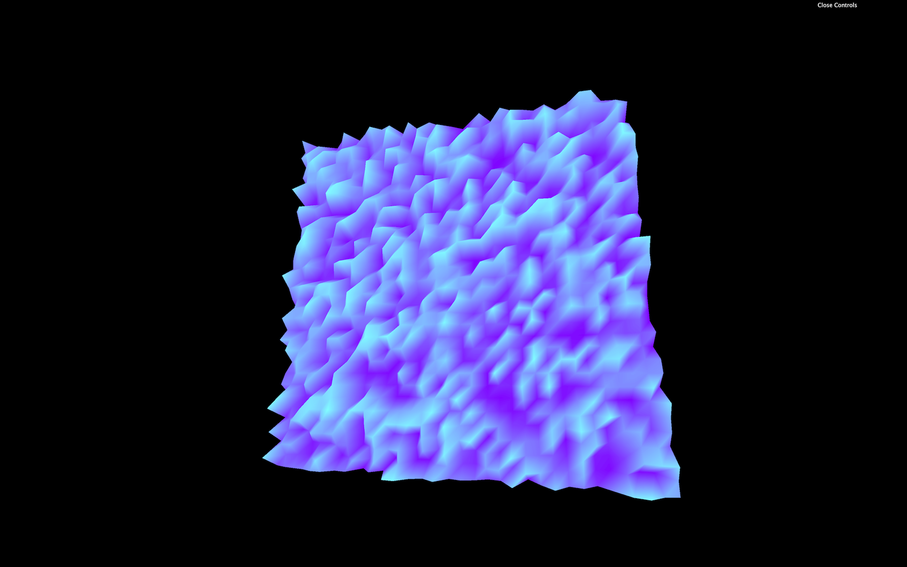
You now obtain a striking looking shape with colored spikes on it.
One interesting thing with varyings is that the values between the vertices are interpolated . If the GPU is drawing a fragment right between two vertices —one having a varying of 1.0 and the other having a varying of 0.0 —the fragment value will be 0.5 .
Let’s remove or comment the elevation part and the varying, so we get back to our purple plane.
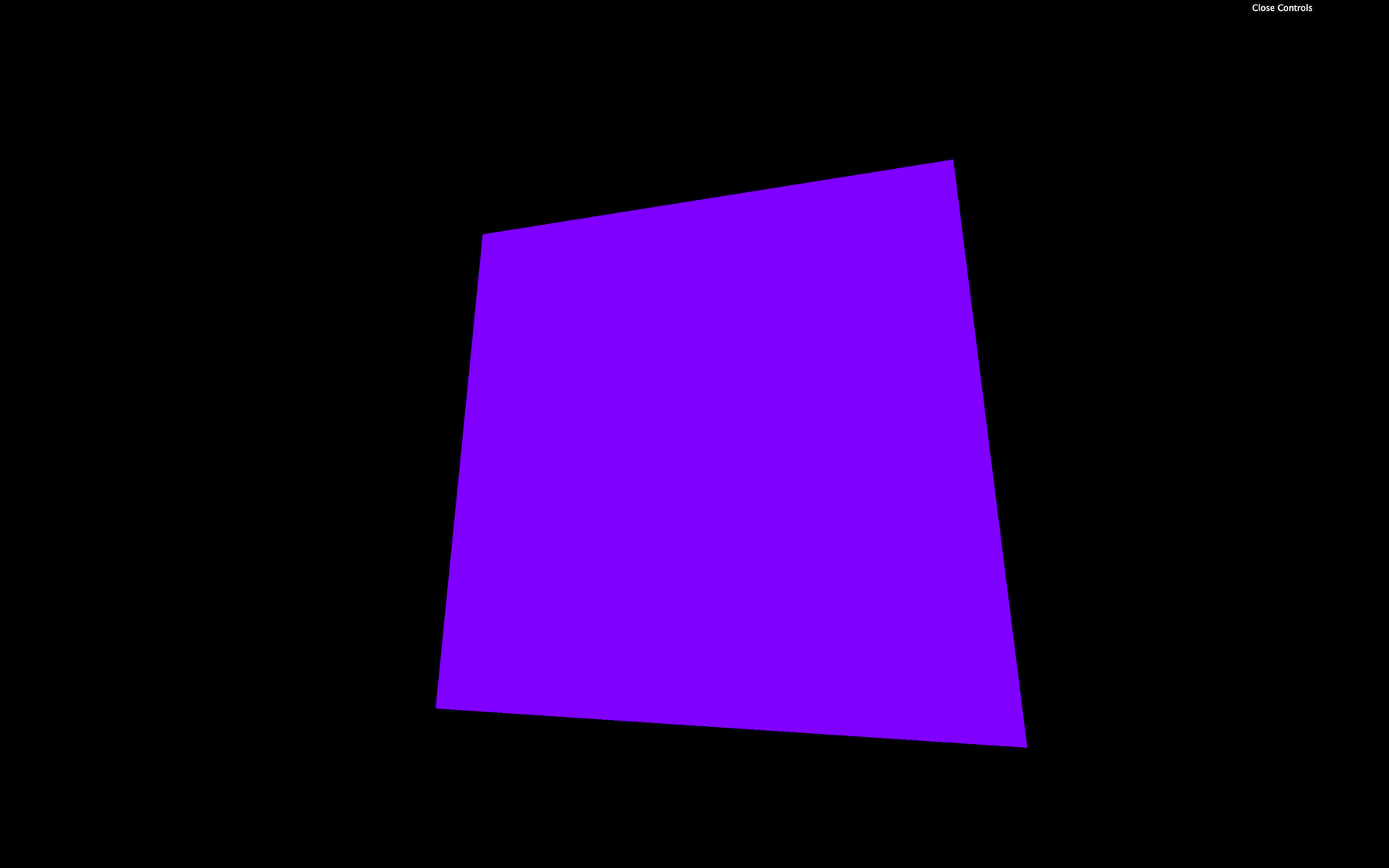
We will use attributes later on.
Uniforms
Uniforms are a way to send data from the JavaScript to the shader.
That can be valuable if we want to use the same shader but with different parameters, and it’s also the occasion to have parameters that can change during the experience.
We can use uniforms with both vertex and fragment shaders, and the data will be the same for every vertex and every fragment. We already have uniforms in our code with projectionMatrix , viewMatrix , and modelMatrix but we didn’t create these. Three.js did.
Let’s create our own uniforms.
To add uniforms to our material , use the uniforms property. We are going to make our plane wave and we want to control the waves frequency:
const material = new THREE.RawShaderMaterial({
    vertexShader: testVertexShader,
    fragmentShader: testFragmentShader,
    uniforms:
    {
        frequency: { value: 10 }
    }
})
JavaScript
Copy
Here, the name of the uniform we chose is frequency . While it’s not mandatory, it’s considered a good practice to prefix with the letter u to distinguish “uniforms” from other data.
Change the name of the uniform to uFrequency :
const material = new THREE.RawShaderMaterial({
    vertexShader: testVertexShader,
    fragmentShader: testFragmentShader,
    uniforms:
    {
        uFrequency: { value: 10 }
    }
})
JavaScript
Copy
If you’re looking at other tutorials or examples, you might see uniforms being declared like this uFrequency: { value: 10, type: 'float' } . There was a time when we had to specify the type but it’s deprecated now.
We can now retrieve the value in our shader code and use it in our main function:
uniform mat4 projectionMatrix;
uniform mat4 viewMatrix;
uniform mat4 modelMatrix;
uniform float uFrequency;

attribute vec3 position;

void main()
{
    // ...
    modelPosition.z += sin(modelPosition.x * uFrequency) * 0.1;

    // ...
}
GLSL
Copy
The result is the same, but we can now control the frequency from the JavaScript.
Let’s change our frequency to a vec2 to control waves horizontally and vertically. We simply use a Three.js Vector2:
const material = new THREE.RawShaderMaterial({
    vertexShader: testVertexShader,
    fragmentShader: testFragmentShader,
    uniforms:
    {
        uFrequency: { value: new THREE.Vector2(10, 5) }
    }
})
JavaScript
Copy
In our shader, we change the float to vec2 , and we apply the displacement on the z axis by using the y axis too:
// ...
uniform vec2 uFrequency;

// ...

void main()
{
    // ...
    modelPosition.z += sin(modelPosition.x * uFrequency.x) * 0.1;
    modelPosition.z += sin(modelPosition.y * uFrequency.y) * 0.1;

    // ...
}
GLSL
Copy
Take your time on this one. It’s easy to make mistakes.
Because those values are now controlled in the JavaScript, we can add them to our Dat.GUI:
gui.add(material.uniforms.uFrequency.value, 'x').min(0).max(20).step(0.01).name('frequencyX')
gui.add(material.uniforms.uFrequency.value, 'y').min(0).max(20).step(0.01).name('frequencyY')
JavaScript
Copy
Let’s add a new uniform to animate our plane like a flag in the wind. We send a time value to the shader by using a uniform and we use this value inside the sin(...) function. First, update the material to add the uTime uniform:
const material = new THREE.RawShaderMaterial({
    vertexShader: testVertexShader,
    fragmentShader: testFragmentShader,
    uniforms:
    {
        uFrequency: { value: new THREE.Vector2(10, 5) },
        uTime: { value: 0 }
    }
})
JavaScript
Copy
Then, update this uTime uniform in the tick function. To do so, use the getElapsedTime function from the Clock to know how much time passed:
const tick = () =>
{
    const elapsedTime = clock.getElapsedTime()

    // Update material
    material.uniforms.uTime.value = elapsedTime

    // ...
}
JavaScript
Copy
Finally, we get the uniform value in our vertex shader, and we use it in the two sin(...) functions:
// ...
uniform float uTime;

// ...

void main()
{
    // ...
    modelPosition.z += sin(modelPosition.x * uFrequency.x + uTime) * 0.1;
    modelPosition.z += sin(modelPosition.y * uFrequency.y + uTime) * 0.1;

    // ...
}
GLSL
Copy
You should see the flag wave as if it was flying the wind.
Let’s invert the direction by using a - before the uTime instead of a + :
    modelPosition.z += sin(modelPosition.x * uFrequency.x - uTime) * 0.1;
    modelPosition.z += sin(modelPosition.y * uFrequency.y - uTime) * 0.1;
GLSL
Copy
Be careful with uTime : if we were to use native JavaScript solution like Date.now() , it wouldn’t work. That is due to Date.now() returning the number of milliseconds spent since January 1st, 1970 and this value is too big for a shader. To put it in a shell, remember that we cannot send uniform values too big or too small.
Don’t forget that this is still a plane and we can transform the Mesh as we used to. Let’s give our plane a flag shape.
We could do it in the shader by multiplying the modelPosition.y value but don’t forget that you can still change the position , scale and rotation directly on the mesh :
const mesh = new THREE.Mesh(geometry, material)
mesh.scale.y = 2 / 3
scene.add(mesh)
JavaScript
Copy
Uniforms are also available in the fragment shader. Let’s add a new uniform to control the color. For a color value, we can use a Three.js a Color:
const material = new THREE.RawShaderMaterial({
    vertexShader: testVertexShader,
    fragmentShader: testFragmentShader,
    uniforms:
    {
        uFrequency: { value: new THREE.Vector2(10, 5) },
        uTime: { value: 0 },
        uColor: { value: new THREE.Color('orange') }
    }
})
JavaScript
Copy
Then, in our fragment shader, we retrieve the value, and we use it inside our gl_FragColor vec4 :
precision mediump float;

uniform vec3 uColor;

void main()
{
    gl_FragColor = vec4(uColor, 1.0);
}
GLSL
Copy
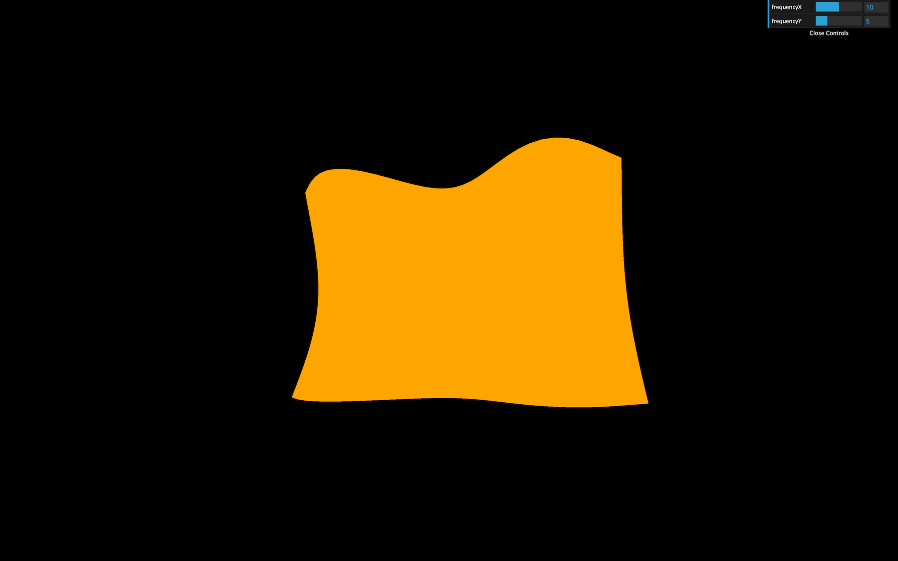
The flag should now be orange.
Textures
Textures are a little harder, but we almost have everything we need.
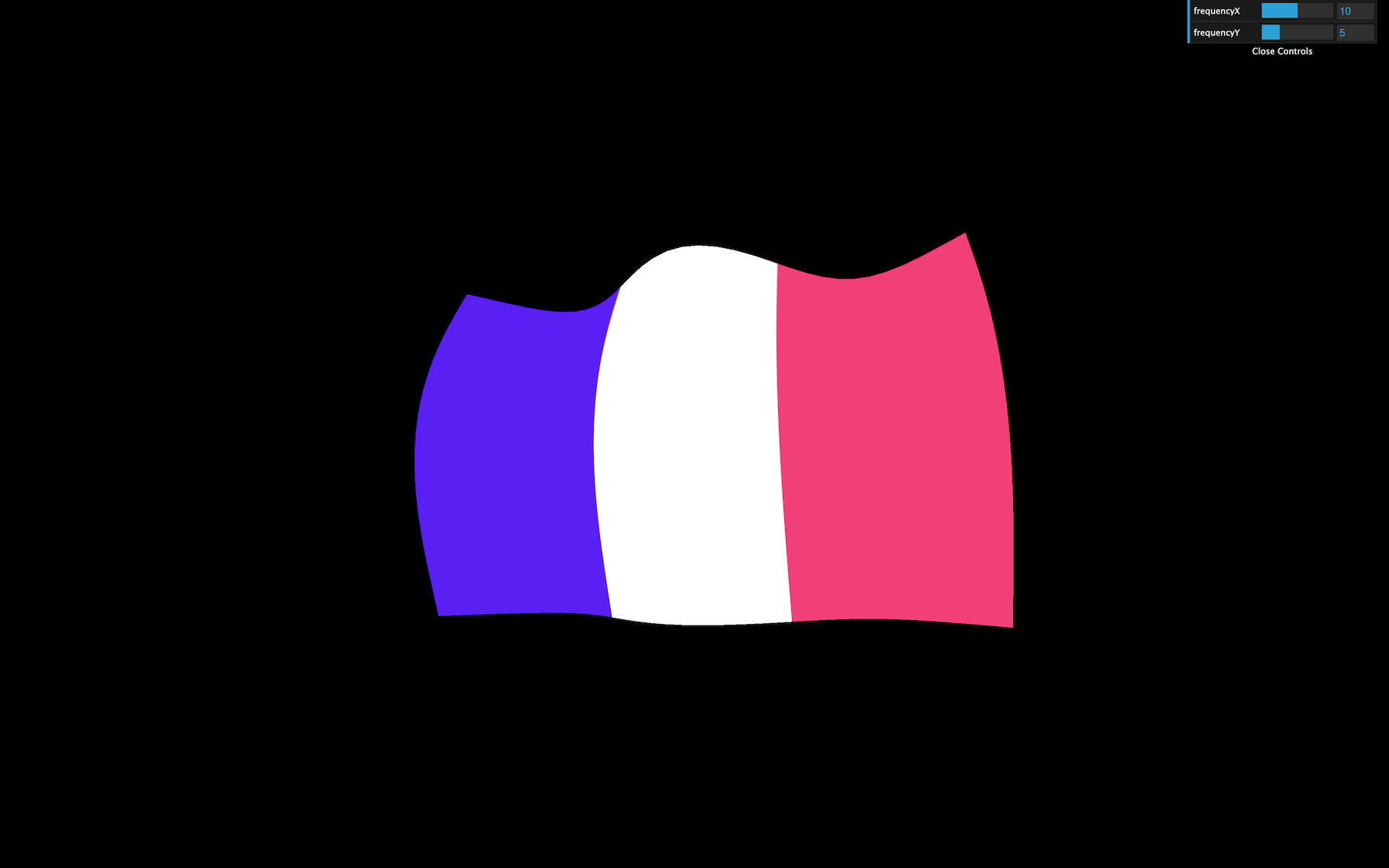
First, we have to load a texture as we did in previous lessons. We already have a flag texture in the /static/textures/ folder and we can use the textureLoader already available in the JavaScript starter:
const flagTexture = textureLoader.load('/textures/flag-french.jpg')
JavaScript
Copy
Then we can send the texture as a uniform. We can call it uTexture :
const material = new THREE.RawShaderMaterial({
    // ...
    uniforms:
    {
        // ...
        uTexture: { value: flagTexture }
    }
})
JavaScript
Copy
While it’s tempting to send it to the fragment shader immediately, we have a problem. To take fragment colors from a texture and apply them in the fragment shader, we must use the texture2D(...) function. The first parameter of texture2D(...) is the texture (easy, it’s our uTexture ), but the second parameter consists of the coordinates of where to pick the color on that texture, and we don’t have these coordinates yet.
That information should sound familiar. We are looking for coordinates that should help us project a texture on a geometry. We are talking about UV coordinates.
The PlaneBufferGeometry automatically generates these coordinates, and we can see that if we log geometry.attributes.uv .
console.log(geometry.attributes.uv)
JavaScript
Copy
Because it’s an attribute, we can retrieve it in the vertex shader:
attribute vec2 uv;
GLSL
Copy
Still, we need those coordinates in the fragment shader. To send data from the vertex shader to the fragment shader, we need to create a varying . We are going to call that varying vUv and update its value in the main function:
// ...
attribute vec2 uv;

varying vec2 vUv;

void main()
{
    // ...

    vUv = uv;
}
GLSL
Copy
We can now retrieve the varying vUv in the fragment shader, retrieve the uniform uTexture and eventually get the fragment color with texture2D(...) :
precision mediump float;

uniform vec3 uColor;
uniform sampler2D uTexture;

varying vec2 vUv;

void main()
{
    vec4 textureColor = texture2D(uTexture, vUv);
    gl_FragColor = textureColor;
}
GLSL
Copy
The output of texture2D(...) is a vec4 because it contains r , g , b ,and a —even if our texture has no alpha variation.
You should get a nice looking flag.
Again, take your time. Doing mistakes here is easy.
Color variations
Our flag color doesn’t vary much. It would be great to have a brightness variation as if there are shadows.
The technique we are going to use isn’t physically accurate, but it should do the trick.
First, in the vertex shader, we are going to store the wind elevation in a variable:
void main()
{
    // ...

    float elevation = sin(modelPosition.x * uFrequency.x - uTime) * 0.1;
    elevation += sin(modelPosition.y * uFrequency.y - uTime) * 0.1;

    modelPosition.z += elevation;

    // ...
}
GLSL
Copy
Then, we send the elevation to the fragment by using a varying:
// ...
varying float vElevation;

void main()
{
    // ...

    vElevation = elevation;
}
GLSL
Copy
Finally, we retrieve the vElevation varying in our fragment shader, and use it to change the r , g , and b properties of our textureColor :
// ...
varying float vElevation;

void main()
{
    vec4 textureColor = texture2D(uTexture, vUv);
    textureColor.rgb *= vElevation * 2.0 + 0.5;
    gl_FragColor = textureColor;
}
GLSL
Copy
You should see brightness variations on the flag as if we had light and shadows. It’s a cheap technique, but it works.
ShaderMaterial
Until now, we have used RawShaderMaterial. The ShaderMaterial works just the same, but with pre-built uniforms and attributes prepended in the shader codes. The precision will also be automatically set.
To use it, simply replace your RawShaderMaterial by ShaderMaterial:
const material = new THREE.ShaderMaterial({
    // ...
JavaScript
Copy
Then remove the following uniform and attribute and precision in both shaders:
uniform mat4 projectionMatrix;uniform mat4 viewMatrix;uniform mat4 modelMatrix;attribute vec3 position;attribute vec2 uv;precision mediump float;
uniform vec2 uFrequency;
uniform float uTime;

attribute float aRandom;

varying float vElevation;
varying vec2 vUv;

void main()
{
    // ...
}
JavaScript
Copy
The shader should work just like before because the ShaderMaterial will add these automatically.
Debugging
Debugging a shader is hard. We cannot log data as in JavaScript because it’s the GPU that execute the shader code and it does it for every vertices and every fragment.
Favorably for us, Three.js is doing a great job passing on the errors at compilation.
Finding the error
If we forget a semicolon, Three.js will log the full shader and tell us the line where the error occurred with a short description like ERROR: 0:71: 'vec4' : syntax error .
This message means that the error occurred at line 71 , but the problem might come from the line right before. Take your time, read the error, and you’ll find what is wrong.
Read the shader
Having the whole shader code logged is also an excellent way to see what Three.js prepends to our shaders when using a ShaderMaterial.
Test values
Another solution to debug values is to use them in the gl_FragColor . That isn’t precise because all we can see are color variations, but sometimes it’s enough.
If the values are in the vertex shader, we can use a varying to pass it on to the fragment shader.
Let’s say we want to see what the uv looks like. We can send it to the fragment with a varying —already done with vUv — and use it in the gl_FragColor :
gl_FragColor = vec4(vUv, 1.0, 1.0);
GLSL
Copy

Go further
Once we understand the basics of the shaders, it’s all about practice. Your first shaders will take countless hours, but you’ll learn techniques that you’ll frequently use.
In the next lessons, we will practice those techniques and even learn how to draw shapes in shaders, but if you want to go further, here are some links:
- The Book of Shaders: https://thebookofshaders.com/
- ShaderToy: https://www.shadertoy.com/
- The Art of Code Youtube Channel: https://www.youtube.com/channel/UCcAlTqd9zID6aNX3TzwxJXg
- Lewis Lepton Youtube Channel: https://www.youtube.com/channel/UC8Wzk_R1GoPkPqLo-obU_kQ
Glslify
GLSLify is a node module that improves what we can do with our glsl files. With glslify, we can import and export glsl codes like modules. That is good to separate our code into multiple smaller and reusable parts.
We won’t be using it in this course, but if your glsl code is getting too big, or let’s say you need the same code in multiple files, you should try adding it to your project.
You can use the glslify-loader and add it to the rules of your webpack configuration.
25 Shader patterns
Difficulty Hard
Introduction
Often, while creating shaders, we need to draw specific patterns like stars, circles, light lenses, waves, etc.
It can help to effectively see those pattern on a geometry or it can be to move the vertices just like we did with the flag in the previous lesson.
We could use textures but drawing the shape gives us more control; we can animate the shape parameters, and there is no texture to load.
It’s much more complicated than drawing with other APIs like canvas because the code is the same for every fragment, and all we have are coordinates and our mathematical skills.
Yes, there will be some maths in this lesson. It’s one of the most frustrating parts for some people but fear not; even if you are doing poorly with maths, you’ll find a solution.
In this lesson, we will try to draw various patterns on a plane. We will start very thoroughly, and things will get more challenging with time. It’s the perfect occasion to discover classic technics and use built-in functions.
For each pattern, we first study the result; then, we try to reproduce it. If you want to get better at this, pause the lesson on each pattern and try to do it yourself. Even if you fail, the solution will make more sense if you tried on you own.
Setup
Currently, we only have one plane on the scene with a ShaderMaterial as a PlaneBufferGeometry. As a reminder, ShaderMaterial is like RawShaderMaterial, with some code prepended to the shaders like importing the matrices, importing some attributes, or setting the precision.
Send the UV coordinates to the fragment
Because we will draw the plane patterns, most of our code will be in the fragment shader. But first, we need to send the UV coordinates from the vertex shader to that fragment shader.
To retrieve the uv attribute in the vertex shader, we should have written something like this:
attribute vec2 uv;
GLSL
Copy
But because we are using a ShaderMaterial, this code is already prepended to the vertex shader.
To send this value from the vertex shader to the fragment shader, we need a varying . We are going to call it vUv and assign it with the uv :
varying vec2 vUv;

void main()
{
    // ...

    vUv = uv;
}
GLSL
Copy
In the fragment shader, we can retrieve this vUv varying with the same declaration:
varying vec2 vUv;

void main()
{
    // ...
}
GLSL
Copy
We now have access to the uv coordinates in our fragment shader as vUv . The values go from 0, 0 on the bottom-left corner to 1, 1 on the top-right corner.
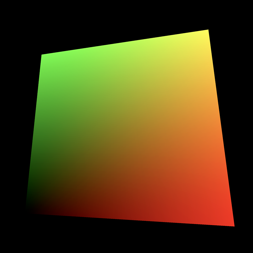
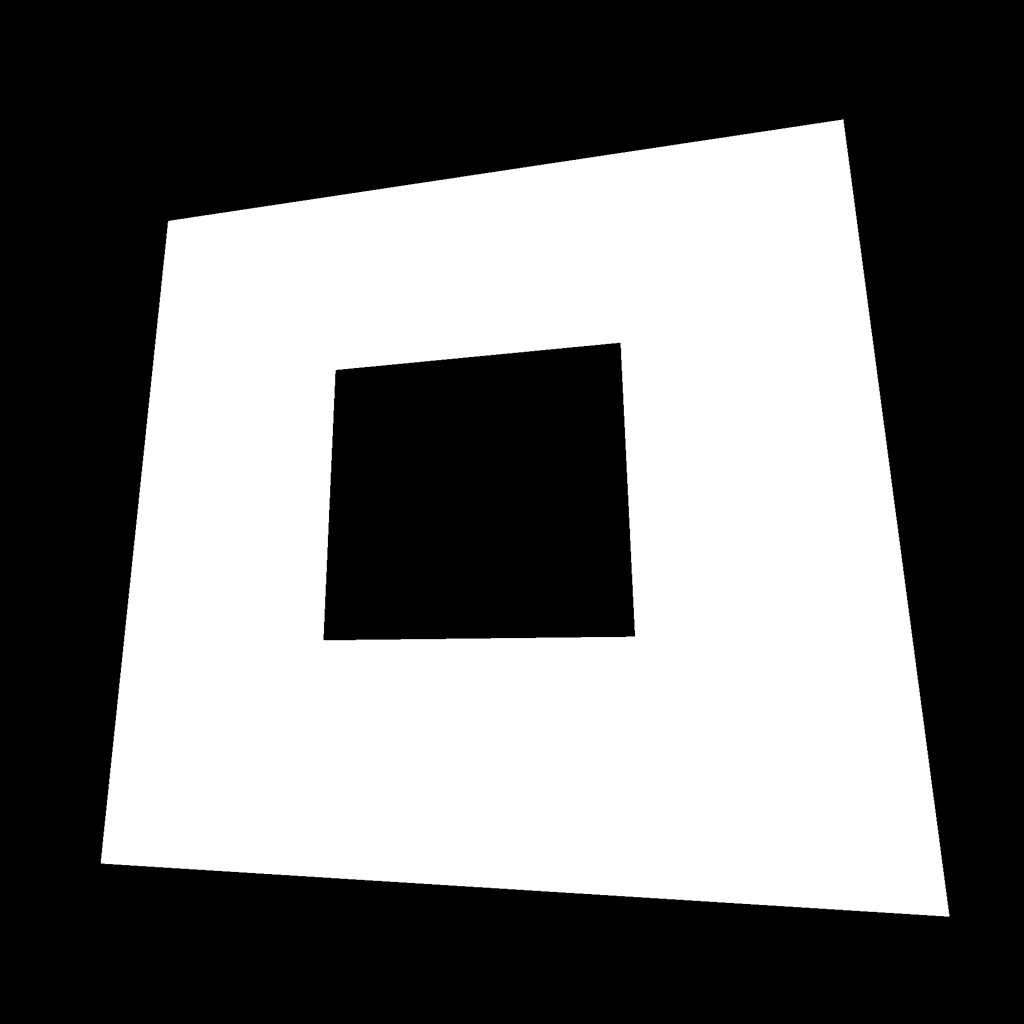
Pattern 1
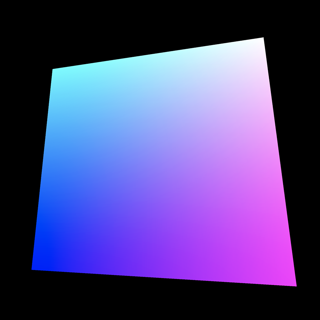
This lovely color pattern is the easiest one to get. We just need to use the vUv in the gl_FragColor with the blue value being 1.0 :
varying vec2 vUv;

void main()
{
    gl_FragColor = vec4(vUv, 1.0, 1.0);
}
GLSL
Copy
Pattern 2
This is exactly the same pattern but with the blue value being 0.0 :
varying vec2 vUv;

void main()
{
    gl_FragColor = vec4(vUv, 0.0, 1.0);
}
GLSL
Copy
Pattern 3
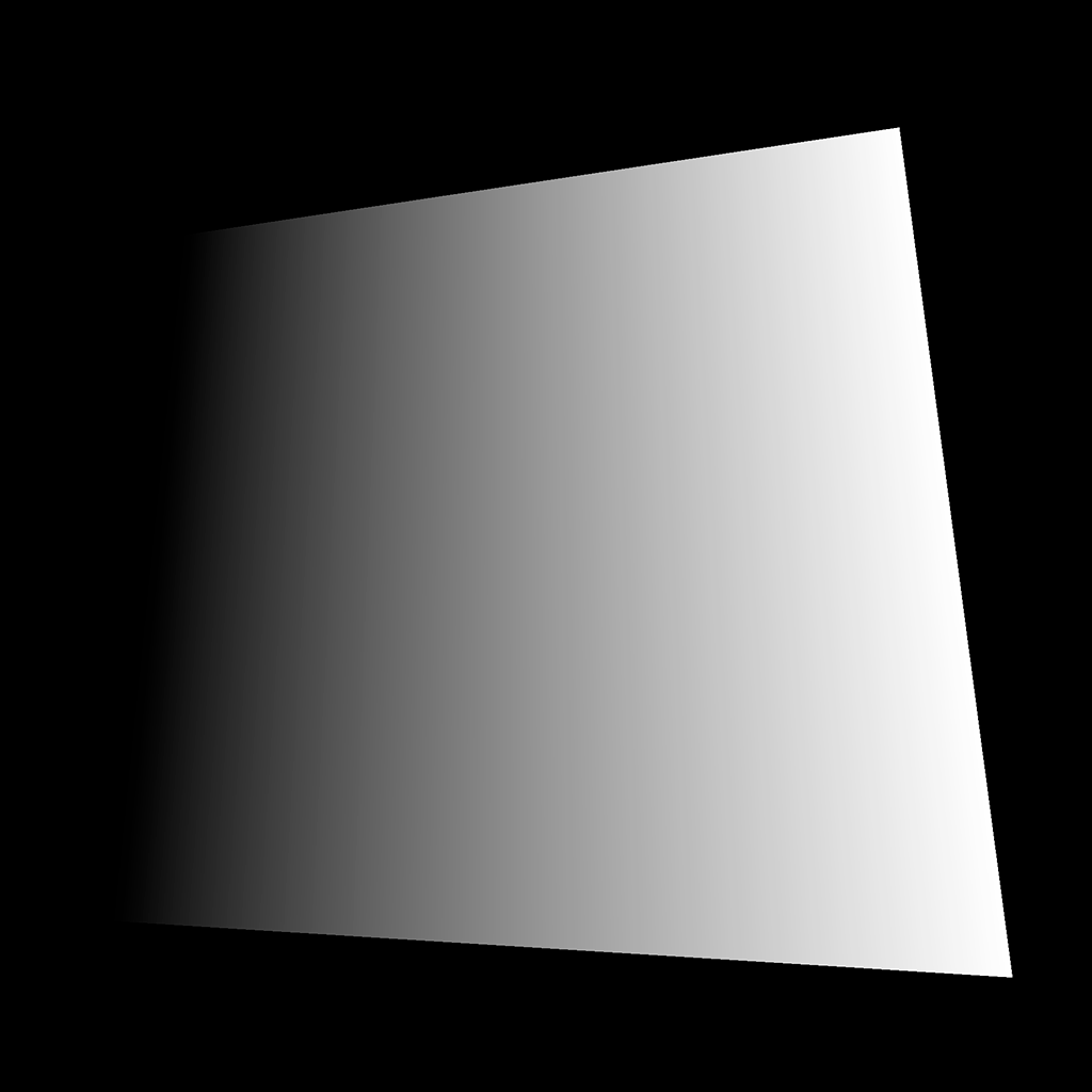
Things get a little more interesting here. To get this gradient, we only use the x property of the vUv , but in all first three values of gl_FragColor :
varying vec2 vUv;

void main()
{
    gl_FragColor = vec4(vUv.x, vUv.x, vUv.x, 1.0);
}
GLSL
Copy
From now, we are going to draw black and white patterns like this. Instead of sending the value on r , g , and b separately, we can create a float variable named strength :
varying vec2 vUv;

void main()
{
    float strength = vUv.x;

    gl_FragColor = vec4(vec3(strength), 1.0);
}
GLSL
Copy
We will now focus on the strength variable and try to draw the following patterns.
Instead of replacing your previous patterns, you can comment so you can get back to them later.
Pattern 4
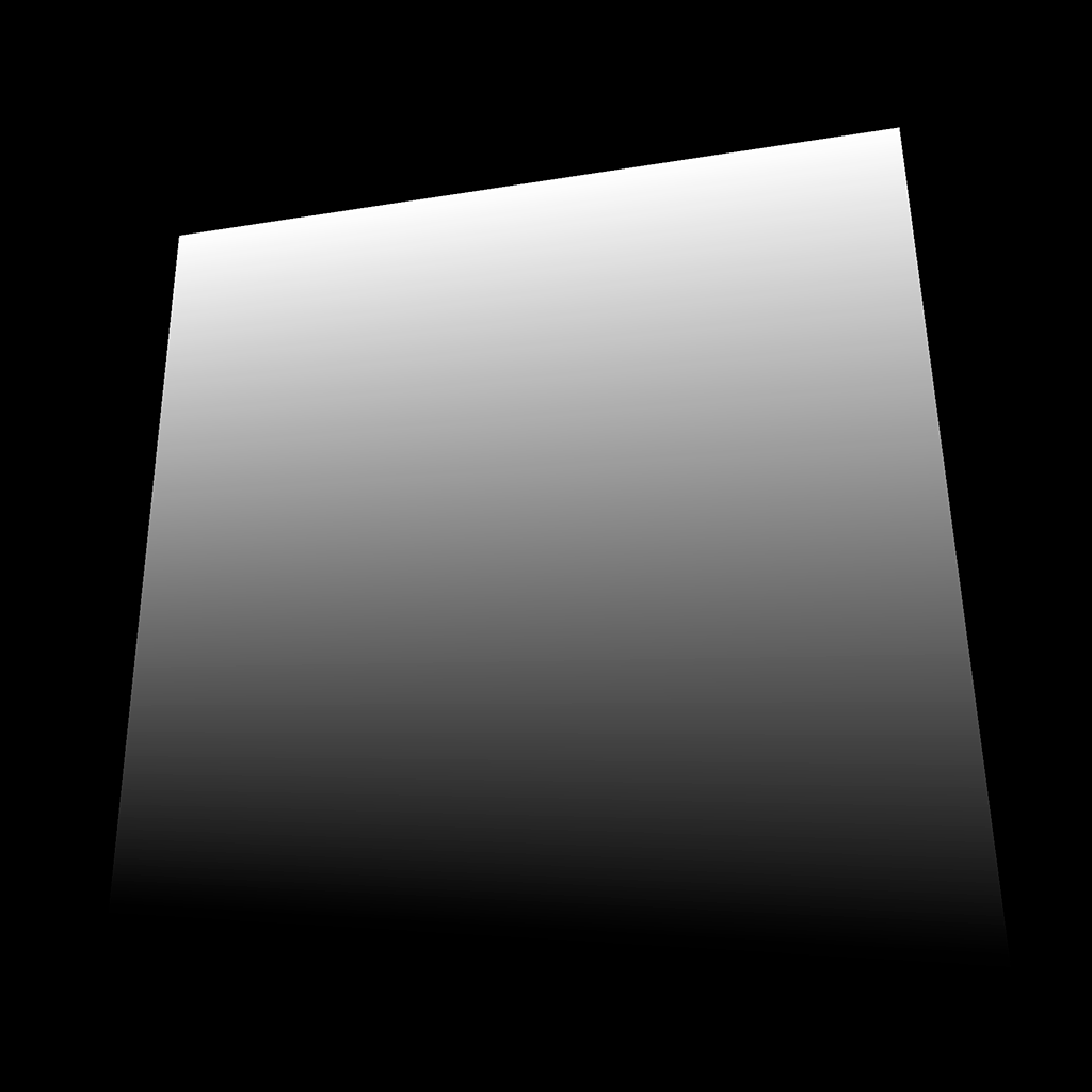
This pattern is exactly the same but on the y axis:
float strength = vUv.y;
GLSL
Copy
Pattern 5
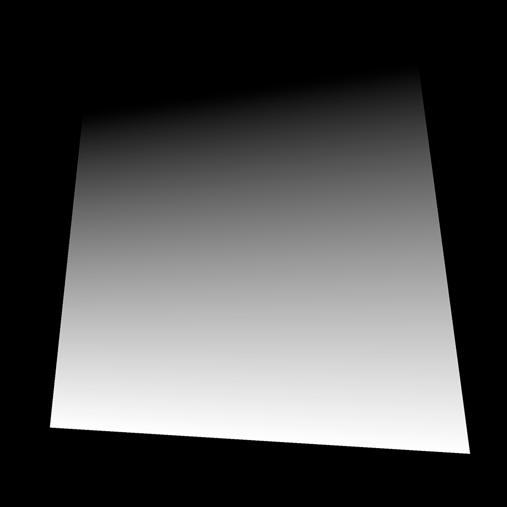
This pattern is exactly the same but we invert the value with 1.0 - ... :
float strength = 1.0 - vUv.y;
GLSL
Copy
Pattern 6

To squeeze the gradient like this, we simply multiply the value. The strength will jump quickly to 1 , but we can’t show a color brighter than white so the rest of the gradient stays white:
float strength = vUv.y * 10.0;
GLSL
Copy
Pattern 7
Now we are talking. To repeat the gradient, we use a modulo. The modulo operation finds the remainder after a division of the first number by the second one.
-
0.5modulo1.0will be0.5 -
0.8modulo1.0will be0.8 -
1.2module1.0will be0.2 -
1.7modulo1.0will be0.7 -
2.0modulo1.0will be0.0 -
2.4modulo1.0will be0.4
It’s like having the first number going back to 0 once it reaches the second number.
In many languages, we can use the % to apply the modulo but in GLSL we have to use the mod(...) function:
float strength = mod(vUv.y * 10.0, 1.0);
GLSL
Copy
Pattern 8

This pattern seems based on the previous one but instead of a gradient, we have 0.0 or 1.0 .
We could have done this with an if statement —because conditions do work in GLSL— but I recommend avoiding conditions for performance reasons.
We can use the step(...) function. We provide an edge value as the first parameter and a number as the second parameter. If the number value is lower than the edge, we get 0.0 . If it’s higher than the edge, we get 1.0 :
float strength = mod(vUv.y * 10.0, 1.0);
strength = step(0.5, strength);
GLSL
Copy
As you can see, we used the step(...) function in another line while re-assigning strength . That has no performance drawback. You’ll see many shader developers write huge code lines with as few variables as possible and almost no comment, but this is just because they know what they are doing.
Do as you want, especially if you are a beginner.
Pattern 9
This pattern is the same as the previous one, but with a higher edge value for the step(...) :
float strength = mod(vUv.y * 10.0, 1.0);
strength = step(0.8, strength);
GLSL
Copy
Pattern 10

This pattern is the same as the previous one but we used the x axis of vUv instead of the y axis:
float strength = mod(vUv.x * 10.0, 1.0);
strength = step(0.8, strength);
GLSL
Copy
Pattern 11

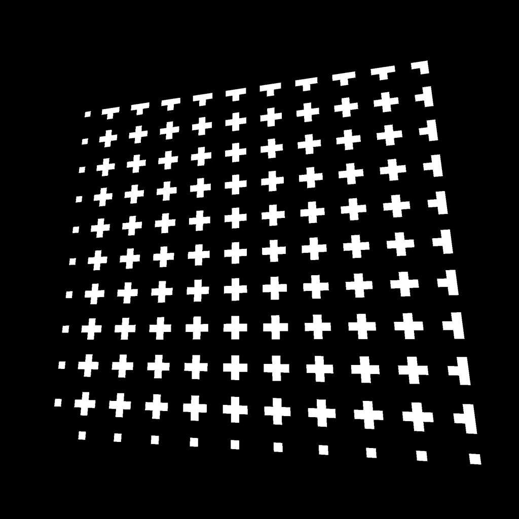
We can also combine them. Here, we have to add the result of the x axis to the result on the y axis:
float strength = step(0.8, mod(vUv.x * 10.0, 1.0));
strength += step(0.8, mod(vUv.y * 10.0, 1.0));
GLSL
Copy
Pattern 12
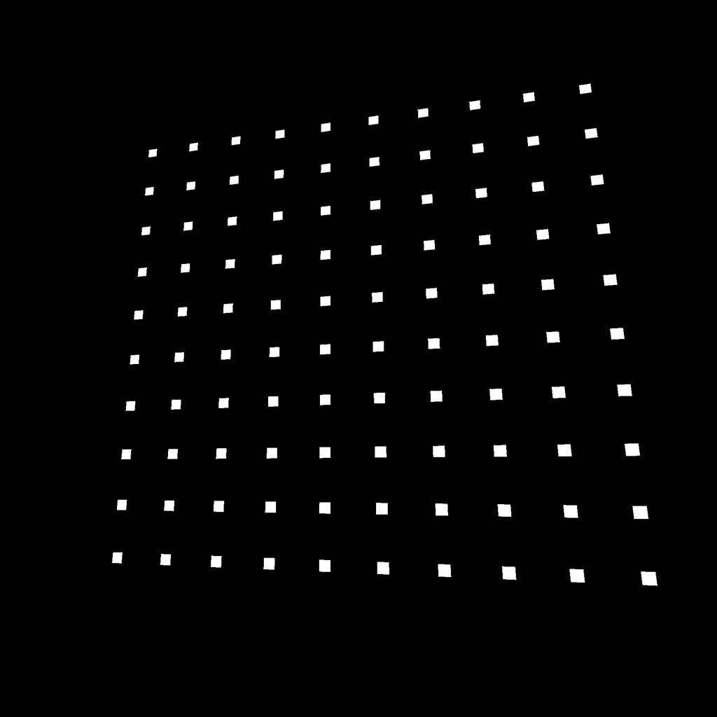
This pattern uses the same principle but with multiplication. We can only see their intersections:
float strength = step(0.8, mod(vUv.x * 10.0, 1.0));
strength *= step(0.8, mod(vUv.y * 10.0, 1.0));
GLSL
Copy
Pattern 13

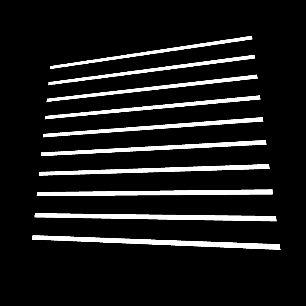
This pattern is the same as before, but we tweaked the step edge on the x axis:
float strength = step(0.4, mod(vUv.x * 10.0, 1.0));
strength *= step(0.8, mod(vUv.y * 10.0, 1.0));
GLSL
Copy
Pattern 14
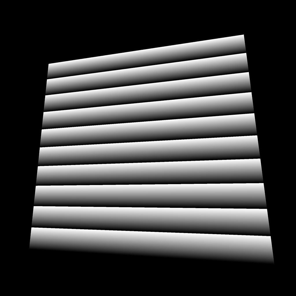
This pattern is a combination of the previous patterns. We create the bars on the x axis and add the bars of the y axis:
float strength = step(0.4, mod(vUv.x * 10.0, 1.0)) * step(0.8, mod(vUv.y * 10.0, 1.0));
strength += step(0.8, mod(vUv.x * 10.0, 1.0)) * step(0.4, mod(vUv.y * 10.0, 1.0));
GLSL
Copy
Like in any languages, when the code gets unbearable like this, it’s a good idea to refactor a little:
float barX = step(0.4, mod(vUv.x * 10.0, 1.0)) * step(0.8, mod(vUv.y * 10.0, 1.0));
float barY = step(0.8, mod(vUv.x * 10.0, 1.0)) * step(0.4, mod(vUv.y * 10.0, 1.0));
float strength = barX + barY;
GLSL
Copy
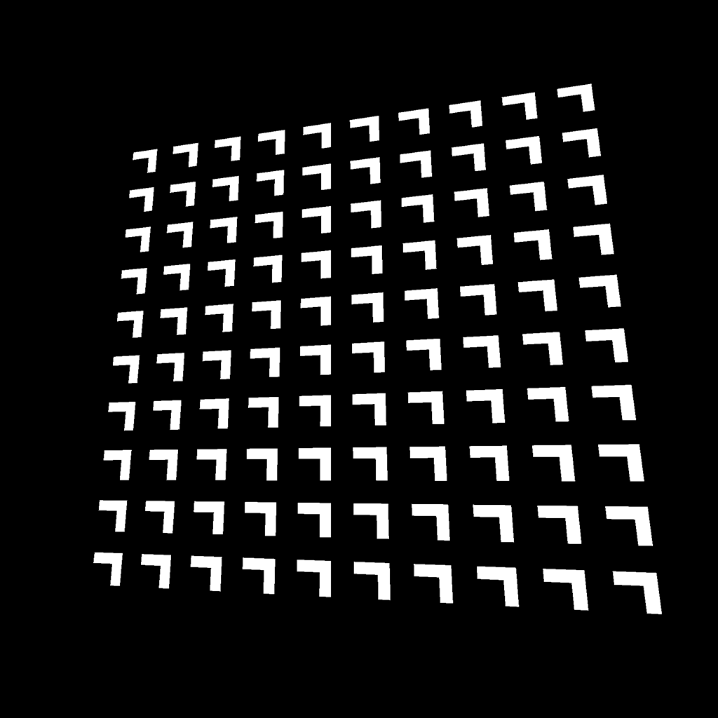
Pattern 15
This pattern is the same as before, but we apply a small offset on the x and y axes of the bars:
float barX = step(0.4, mod(vUv.x * 10.0 - 0.2, 1.0)) * step(0.8, mod(vUv.y * 10.0, 1.0));
float barY = step(0.8, mod(vUv.x * 10.0, 1.0)) * step(0.4, mod(vUv.y * 10.0 - 0.2, 1.0));
float strength = barX + barY;
GLSL
Copy
That is the kind of situation where beginners like us will stick to tweaking the values until it works. There is no problem with that, and the solution will probably make sense once you find it.
Pattern 16
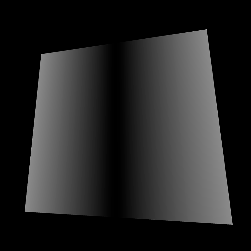
Let’s go in another direction with this one. To get this result, we first need to offset the vUv.x so it goes from -0.5 to 0.5 . Then we need the value to be always positive so it goes from 0.5 to 0.0 to 0.5 again. For this, we can use the abs(...) function:
float strength = abs(vUv.x - 0.5);
GLSL
Copy
Pattern 17
This pattern looks like a combination of the previous one combines with a variation on the y axis. It’s no ordinary combination. What you can see here is the minimum value between the pattern on the x axis and the pattern on the y axis. To do that, we use the min(...) function:
float strength = min(abs(vUv.x - 0.5), abs(vUv.y - 0.5));
GLSL
Copy
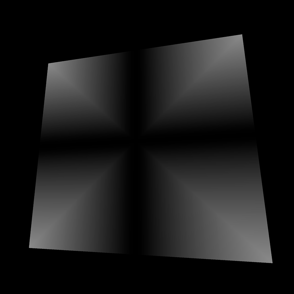
Pattern 18
Same thing as above, but with the max(...) function:
float strength = max(abs(vUv.x - 0.5), abs(vUv.y - 0.5));
GLSL
Copy
Pattern 19
For this pattern, we simply applied a step(...) on the previous value:
float strength = step(0.2, max(abs(vUv.x - 0.5), abs(vUv.y - 0.5)));
GLSL
Copy
Pattern 20

This pattern is the multiplication of one square with another but smaller and inverted.
float strength = step(0.2, max(abs(vUv.x - 0.5), abs(vUv.y - 0.5)));
strength *= 1.0 - step(0.25, max(abs(vUv.x - 0.5), abs(vUv.y - 0.5)));
GLSL
Copy
Pattern 21

For this pattern, we multiply vUv.x by 10.0 , round it to its lower integer with the floor(...) function, and divide it by 10.0 to get a value between 0.0 , and 1.0 :
float strength = floor(vUv.x * 10.0) / 10.0;
GLSL
Copy
Pattern 22
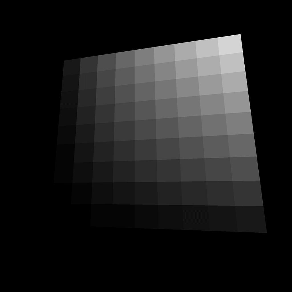
As before, we can combine the different axes by multiplying them:
float strength = floor(vUv.x * 10.0) / 10.0 * floor(vUv.y * 10.0) / 10.0;
GLSL
Copy
Pattern 23
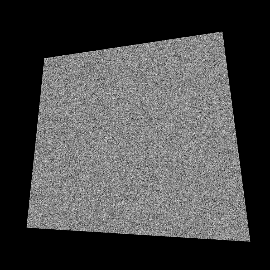
Getting this pattern is complicated because there is no native random function in GLSL. The trick is to get a value so unpredictable that it looks random.
One popular way to get that kind of value is using the following function:
float random(vec2 st)
{
    return fract(sin(dot(st.xy, vec2(12.9898,78.233))) * 43758.5453123);
}
GLSL
Copy
We provide a vec2 to this function, and we get a pseudo random value.
If you want to learn more about this function, here’s a link from The Book of Shaders : https://thebookofshaders.com/10/
We can add this function outside of the main function, and use it with the vUv :
varying vec2 vUv;

float random(vec2 st)
{
    return fract(sin(dot(st.xy, vec2(12.9898,78.233))) * 43758.5453123);
}

void main()
{
    // ...

    float strength = random(vUv);

    // ...
}
GLSL
Copy
Be careful with this random function. Using the wrong values can result in noticeable shapes in the randomness.
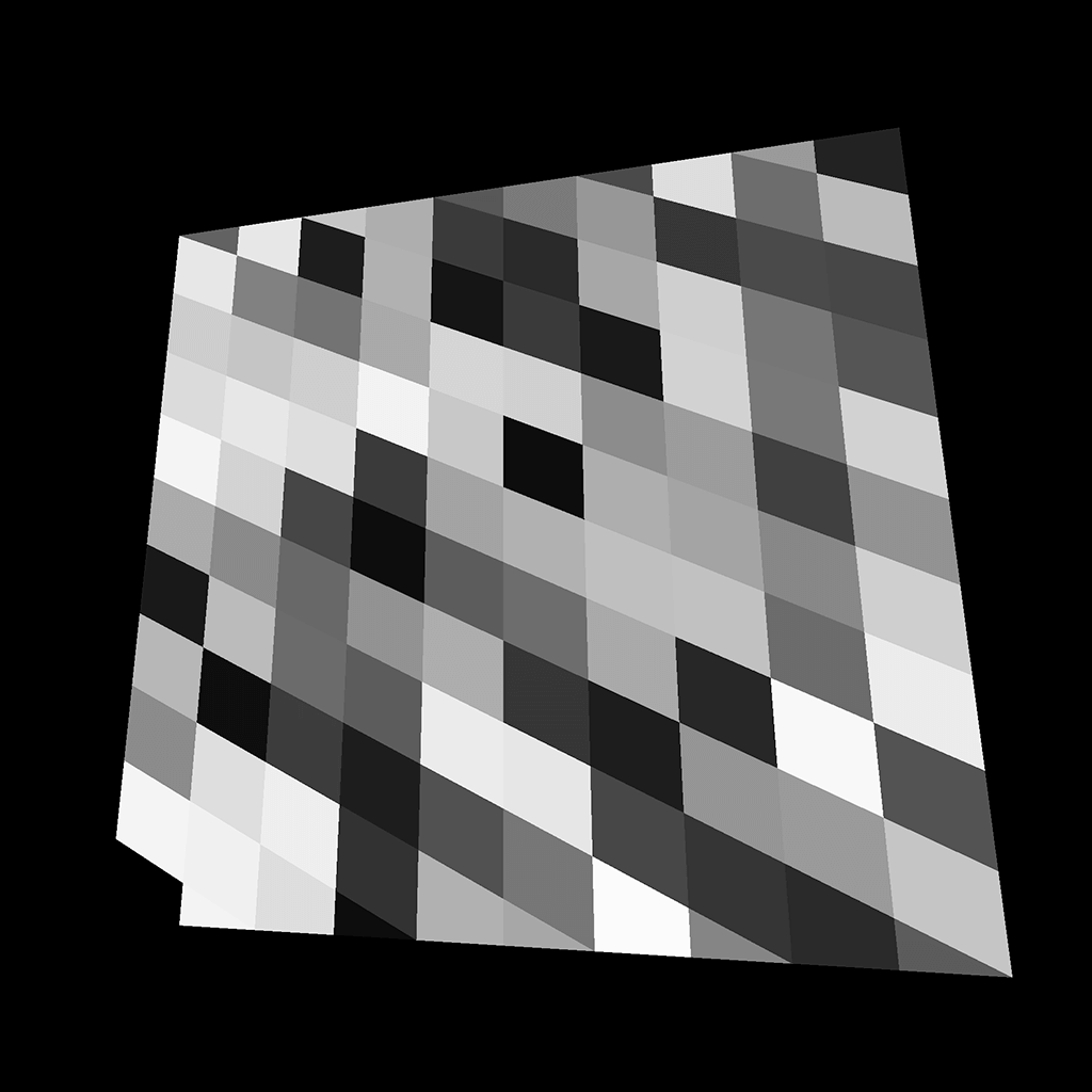
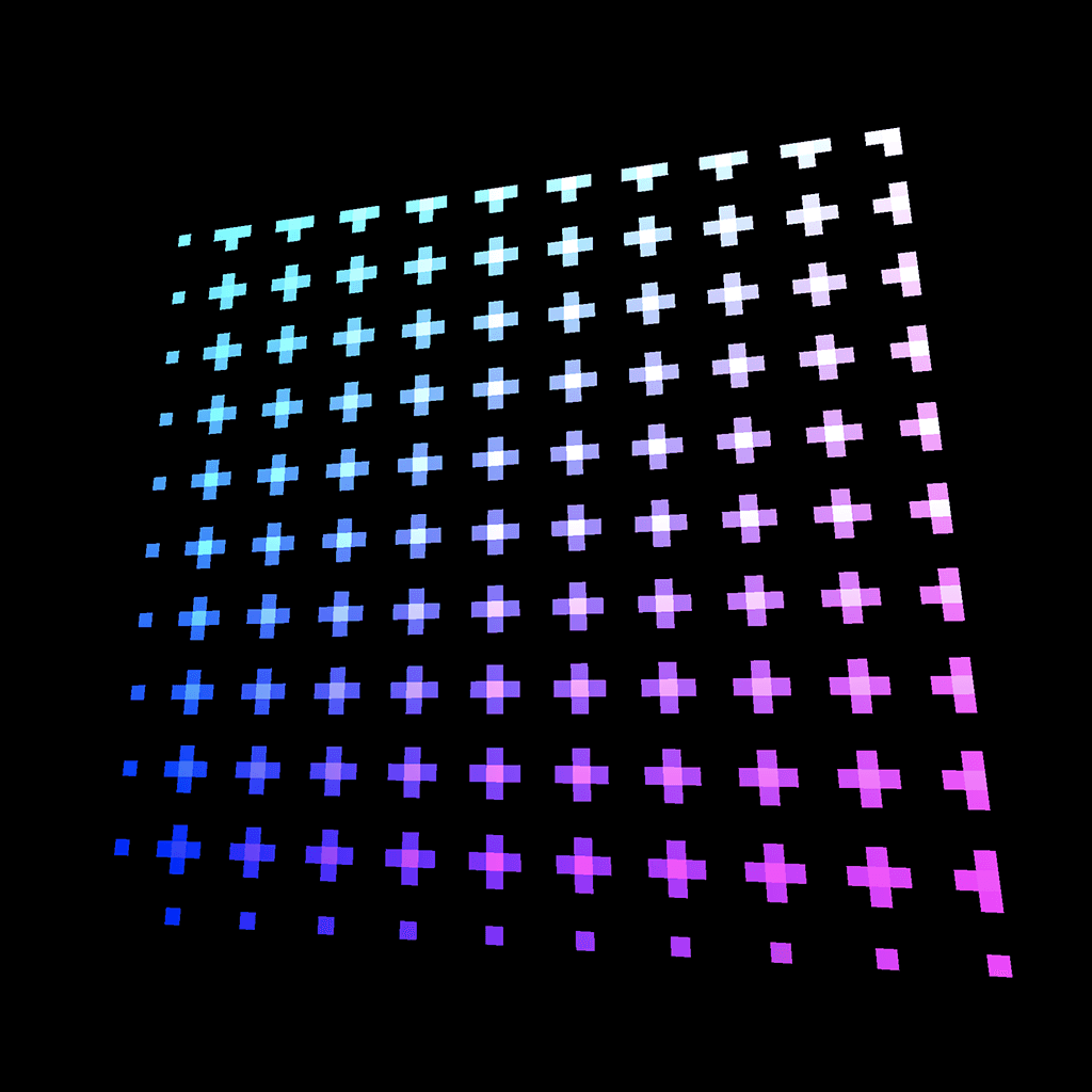
Pattern 24
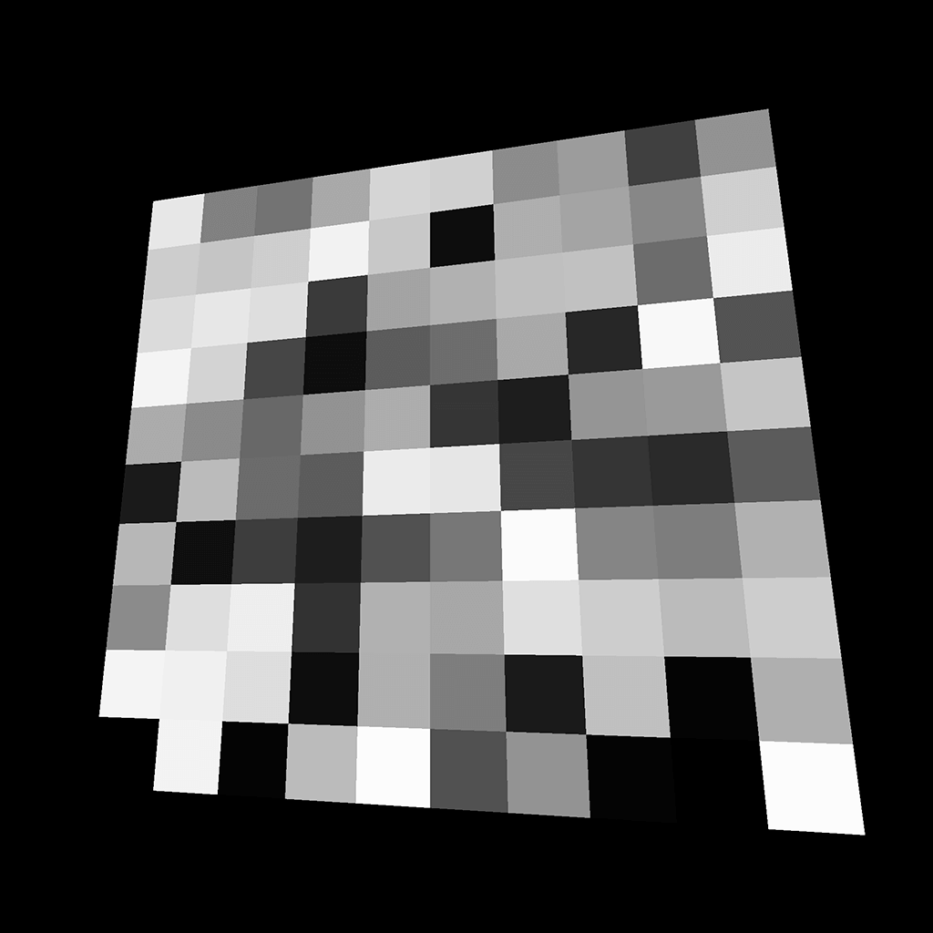
This pattern is a combination of the two previous ones. First, we create a new vec2 coordinates named gridUv with rounded values:
vec2 gridUv = vec2(floor(vUv.x * 10.0) / 10.0, floor(vUv.y * 10.0) / 10.0);
GLSL
Copy
Then, we use these coordinates with the random function:
float strength = random(gridUv);
GLSL
Copy
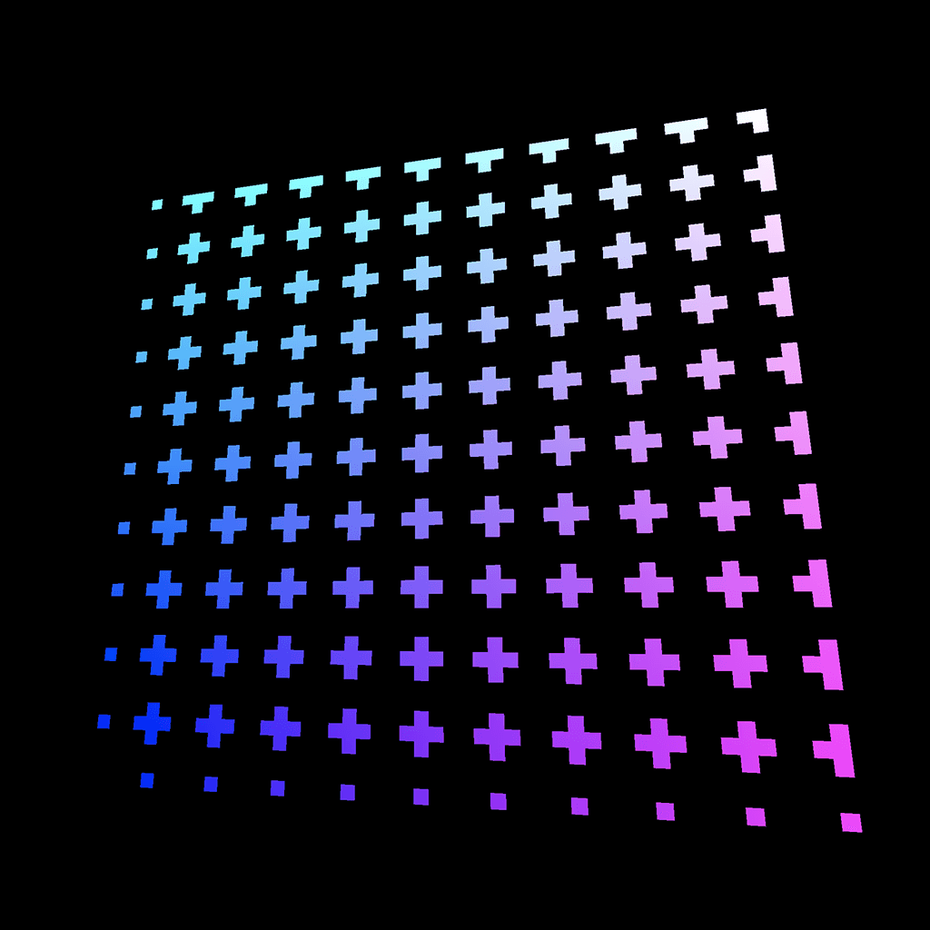
Pattern 25
This pattern stems from the previous one. To get this tilt effect, we must add the vUv.x to the vUv.y when creating the gridUv :
vec2 gridUv = vec2(floor(vUv.x * 10.0) / 10.0, floor((vUv.y + vUv.x * 0.5) * 10.0) / 10.0);
float strength = random(gridUv);
GLSL
Copy
Pattern 26
On this pattern, the further from the bottom left corner, the brighter the strength is.
That is in fact the length of the vUv . vUv value is equal to 0.0, 0.0 so the length is 0.0 on the bottom-left corner and the further we go away from that corner, the higher its length is.
We can get the length of a vector ( vec2 , vec3 or vec4 ) with the length(...) function:
float strength = length(vUv);
GLSL
Copy
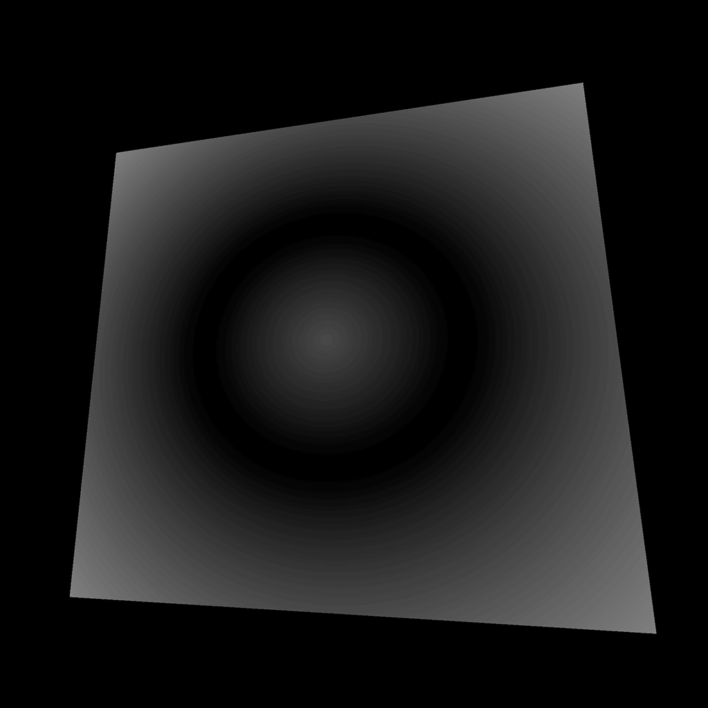
Pattern 27
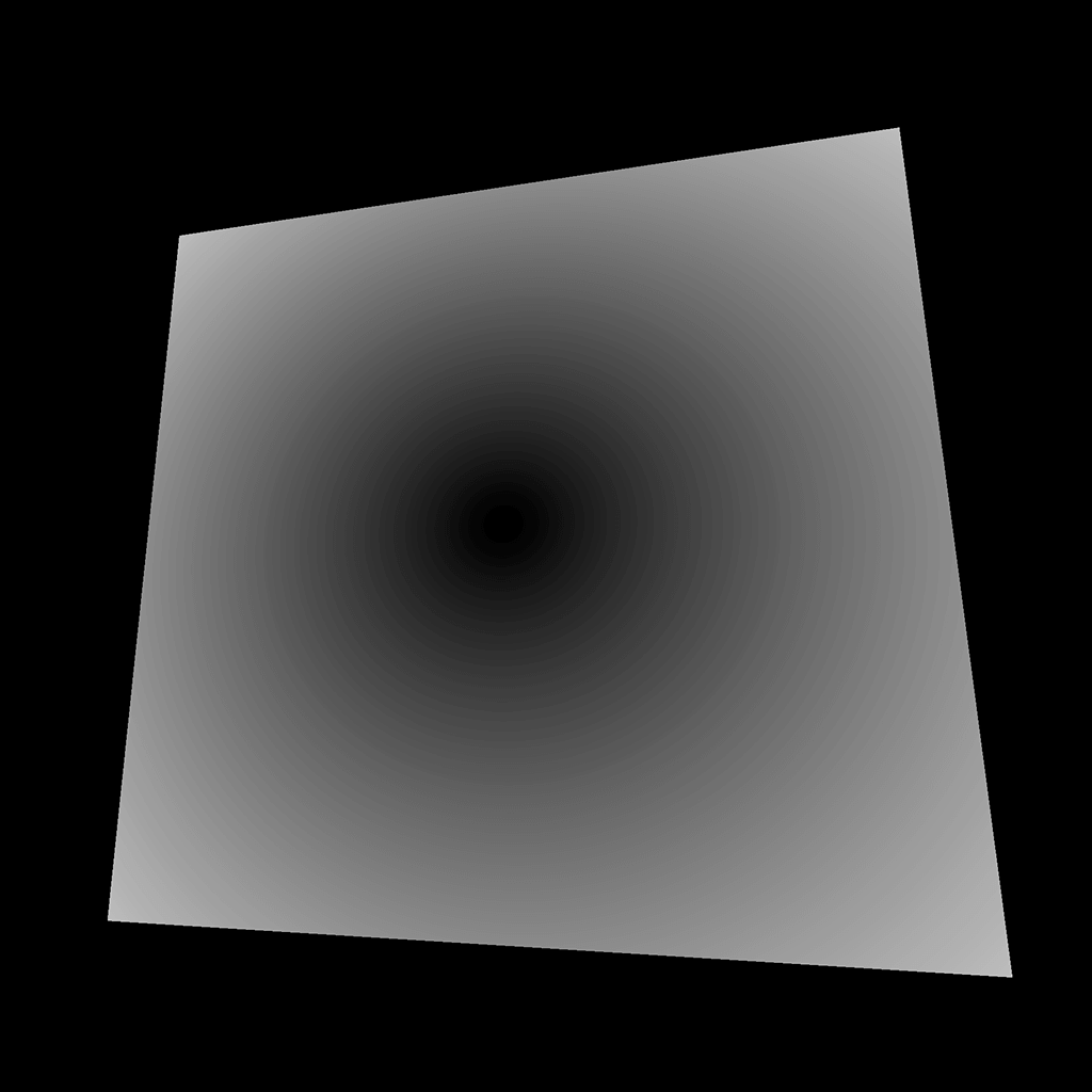
Instead, we will get the distance between vUv and the center of our plane. Because our plane UV goes from 0.0, 0.0 to 1.0, 1.0 , the center is 0.5, 0.5 . We are going to create a vec2 corresponding to the center and get the distance from the vUv with the distance(...) function:
float strength = distance(vUv, vec2(0.5));
GLSL
Copy
When creating a vector with only one value, this value will be passed on every properties — x and y in our case.
Be aware that we could also have offset the vUv and use the length(...) function.
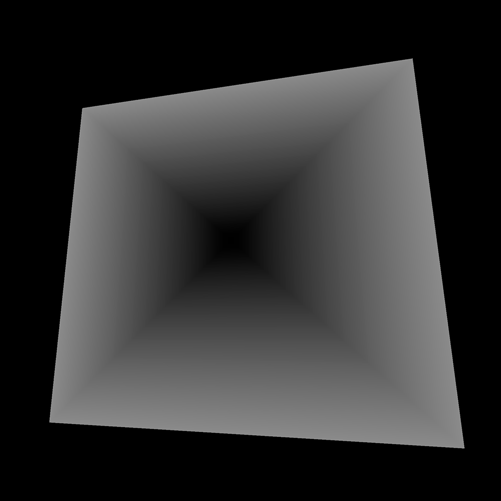
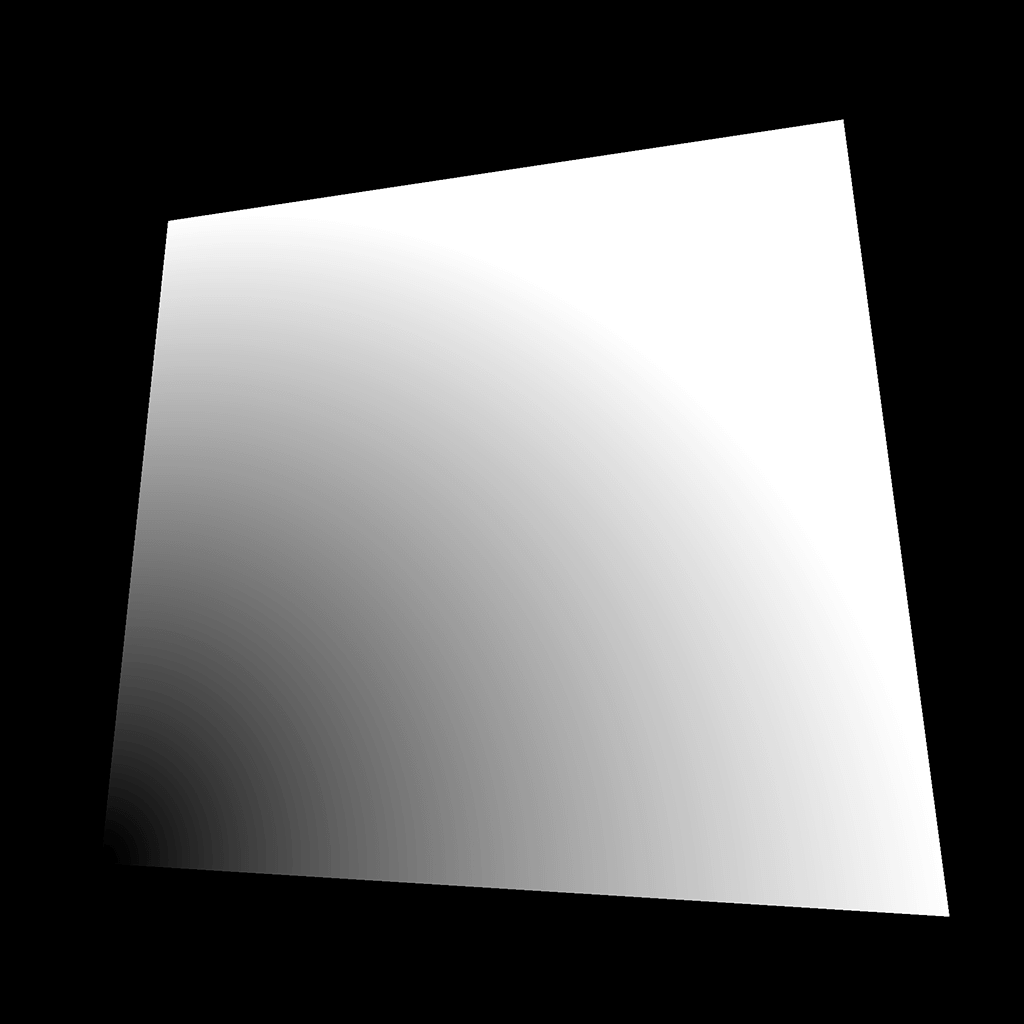
Pattern 28
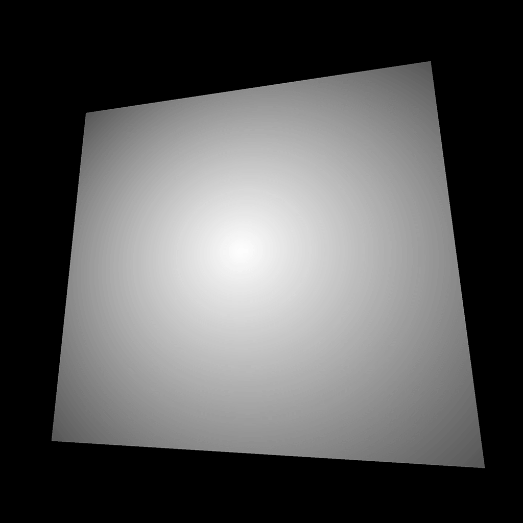
For this pattern, we subtract the previous value to 1.0 :
float strength = 1.0 - distance(vUv, vec2(0.5));
GLSL
Copy
Pattern 29
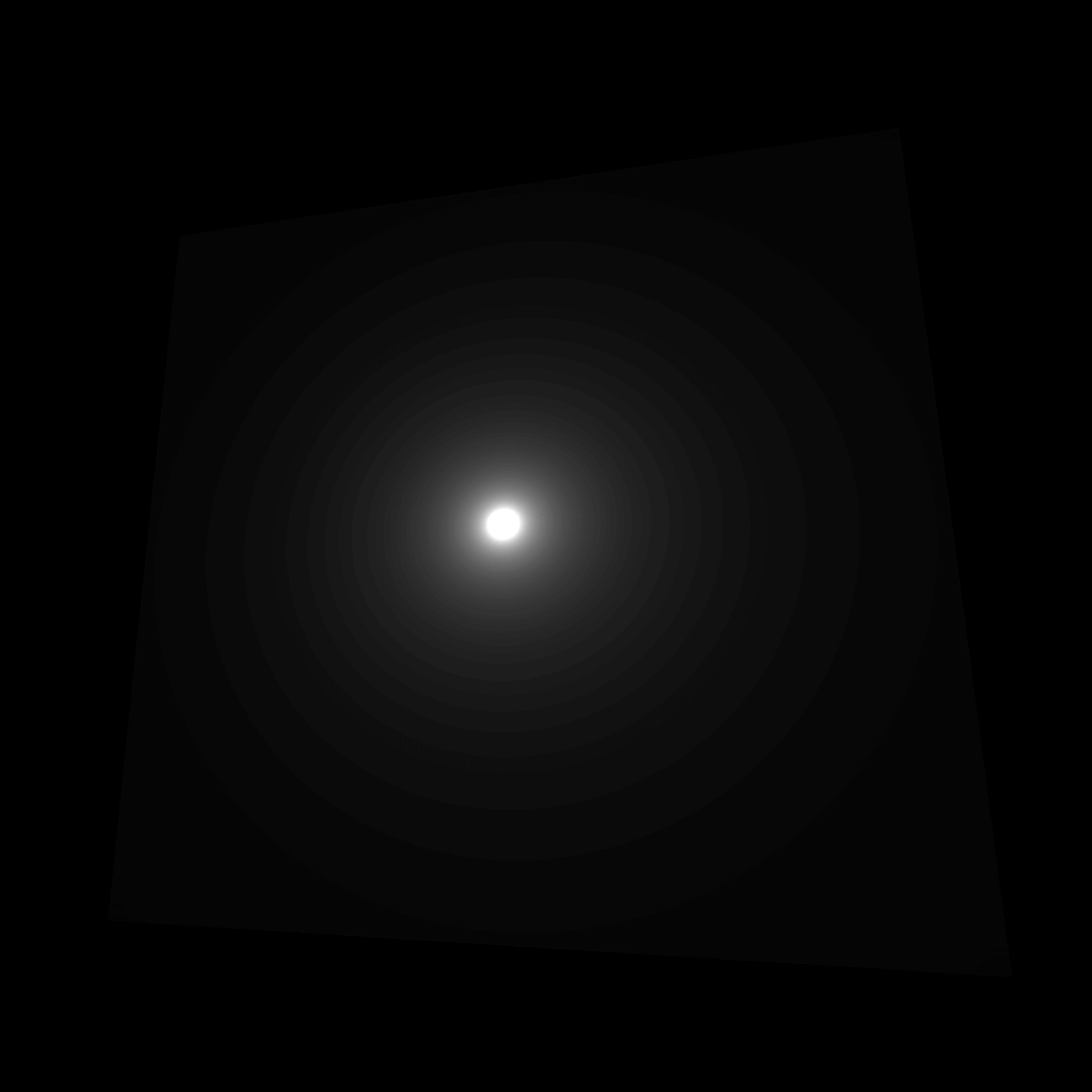
This pattern is handy when creating a light lens effect. To get this result, we start from a small value and divide it by the previously calculated distance:
float strength = 0.015 / (distance(vUv, vec2(0.5)));
GLSL
Copy
Pattern 30
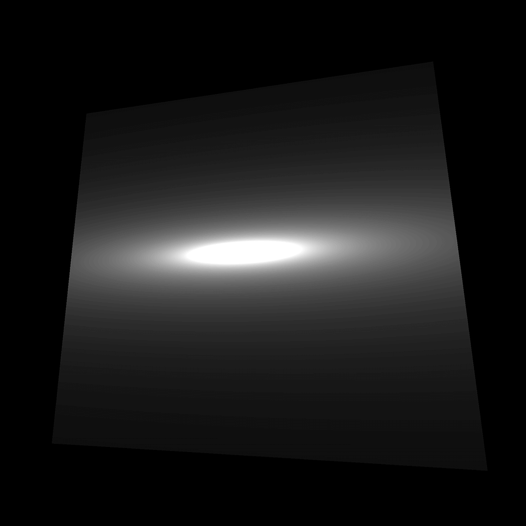
This is the same pattern but with the UV squeezed and moved on the y axis only:
float strength = 0.15 / (distance(vec2(vUv.x, (vUv.y - 0.5) * 5.0 + 0.5), vec2(0.5)));
GLSL
Copy
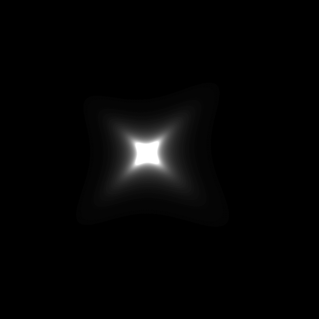
Pattern 31

And this is the same pattern multiplied with the same formula, but this second one is based on the x axis:
float strength = 0.15 / (distance(vec2(vUv.x, (vUv.y - 0.5) * 5.0 + 0.5), vec2(0.5)));
strength *= 0.15 / (distance(vec2(vUv.y, (vUv.x - 0.5) * 5.0 + 0.5), vec2(0.5)));
GLSL
Copy
Pattern 32
Getting this pattern is rather laborious. We need to rotate the vUv coordinates in the center. Doing a 2D rotation is a mix of cos(...) and sin(...) that we won’t cover here. It’s also a good opportunity to use functions. Add this following function before the main function:
vec2 rotate(vec2 uv, float rotation, vec2 mid)
{
    return vec2(
      cos(rotation) * (uv.x - mid.x) + sin(rotation) * (uv.y - mid.y) + mid.x,
      cos(rotation) * (uv.y - mid.y) - sin(rotation) * (uv.x - mid.x) + mid.y
    );
}
GLSL
Copy
Then, we can use it to create a new set of UV that we will call rotatedUV . The problem is that we want to rotate exactly one-eighth of a full circle. Regrettably, we don’t have access to π (pi) in GLSL.
Instead, we can create a variable that contains an approximation to π:
float pi = 3.1415926535897932384626433832795;
GLSL
Copy
Because this variable will never change, we can save it as a define at the start of the code:
#define PI 3.1415926535897932384626433832795
GLSL
Copy
Defines are cheaper than variables but cannot be changed. It is good practice to right defines in UPPERCASE to distinguish them from other variables.
Then we can use that PI value for the second parameter of the rotate(...) function (the angle):
vec2 rotatedUv = rotate(vUv, PI * 0.25, vec2(0.5));
GLSL
Copy
And finally, we replace our vUv by this new rotatedUV :
float strength = 0.15 / (distance(vec2(rotatedUv.x, (rotatedUv.y - 0.5) * 5.0 + 0.5), vec2(0.5)));
strength *= 0.15 / (distance(vec2(rotatedUv.y, (rotatedUv.x - 0.5) * 5.0 + 0.5), vec2(0.5)));
GLSL
Copy
Pattern 33
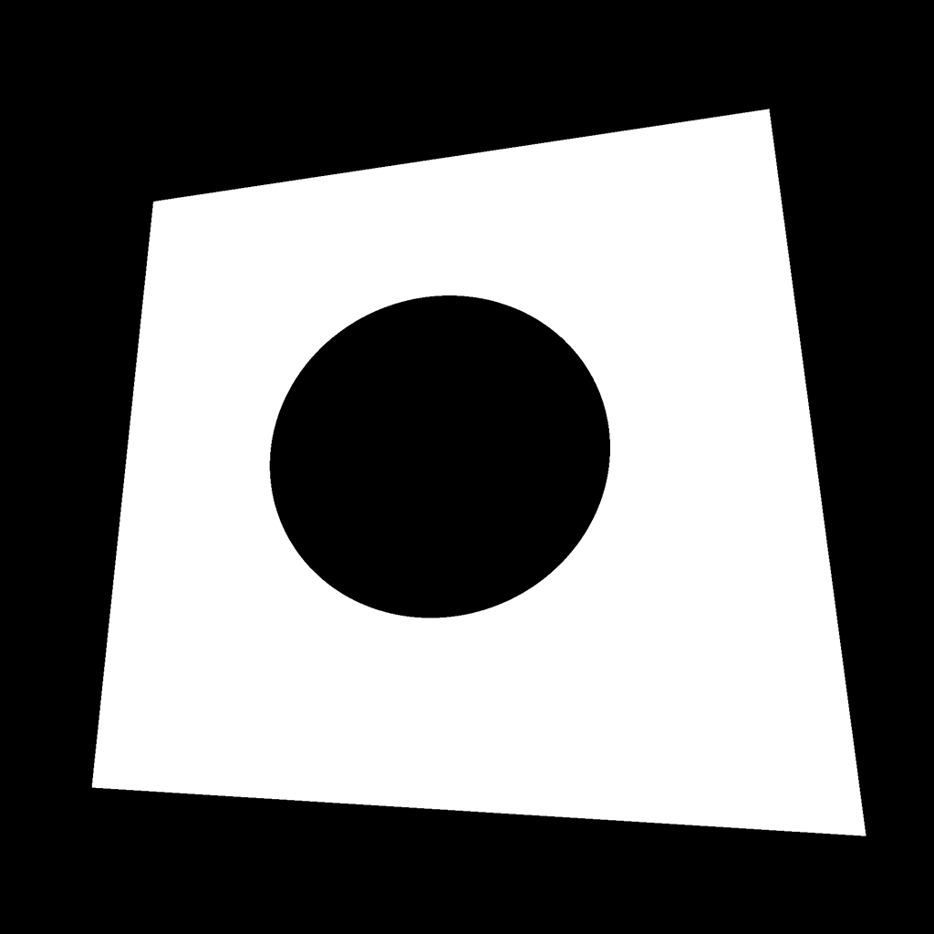
To draw that disc, we use the distance(...) function with the step(...) function and apply an offset to control the disc radius:
float strength = step(0.5, distance(vUv, vec2(0.5)) + 0.25);
GLSL
Copy
We could also have change the first parameter of step(...) —named edge— to control the radius.
Pattern 34
This pattern is very close to the previous one, but we use the abs(...) function to keep a positive value:
float strength = abs(distance(vUv, vec2(0.5)) - 0.25);
GLSL
Copy
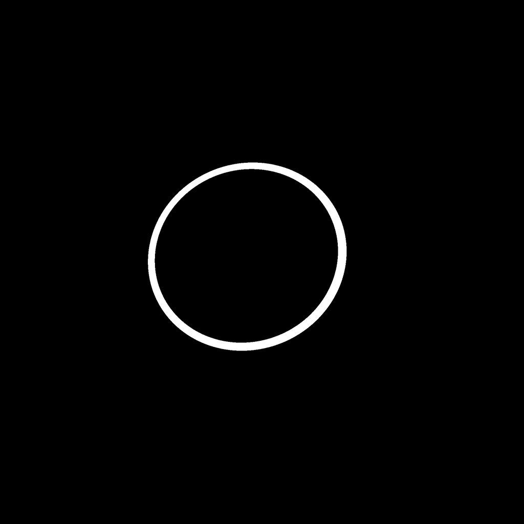
Pattern 35
We can combine the two previous ones to get a circle:
float strength = step(0.02, abs(distance(vUv, vec2(0.5)) - 0.25));
GLSL
Copy
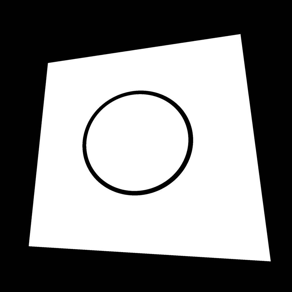
Pattern 36
And we can invert it with 1.0 - ... :
float strength = 1.0 - step(0.01, abs(distance(vUv, vec2(0.5)) - 0.25));
GLSL
Copy
Pattern 37
This pattern is based on the previous one, but with a wave-like distortion. To get this result, we create a new UV variable that we can call wavedUv , and we add a sin(...) based on the x axis to the y value:
vec2 wavedUv = vec2(
    vUv.x,
    vUv.y + sin(vUv.x * 30.0) * 0.1
);
GLSL
Copy
Then, we use that wavedUv instead of the vUv :
float strength = 1.0 - step(0.01, abs(distance(wavedUv, vec2(0.5)) - 0.25));
GLSL
Copy
Pattern 38
For this pattern, we also apply the wave distortion to the x axis:
vec2 wavedUv = vec2(
    vUv.x + sin(vUv.y * 30.0) * 0.1,
    vUv.y + sin(vUv.x * 30.0) * 0.1
);
float strength = 1.0 - step(0.01, abs(distance(wavedUv, vec2(0.5)) - 0.25));
GLSL
Copy
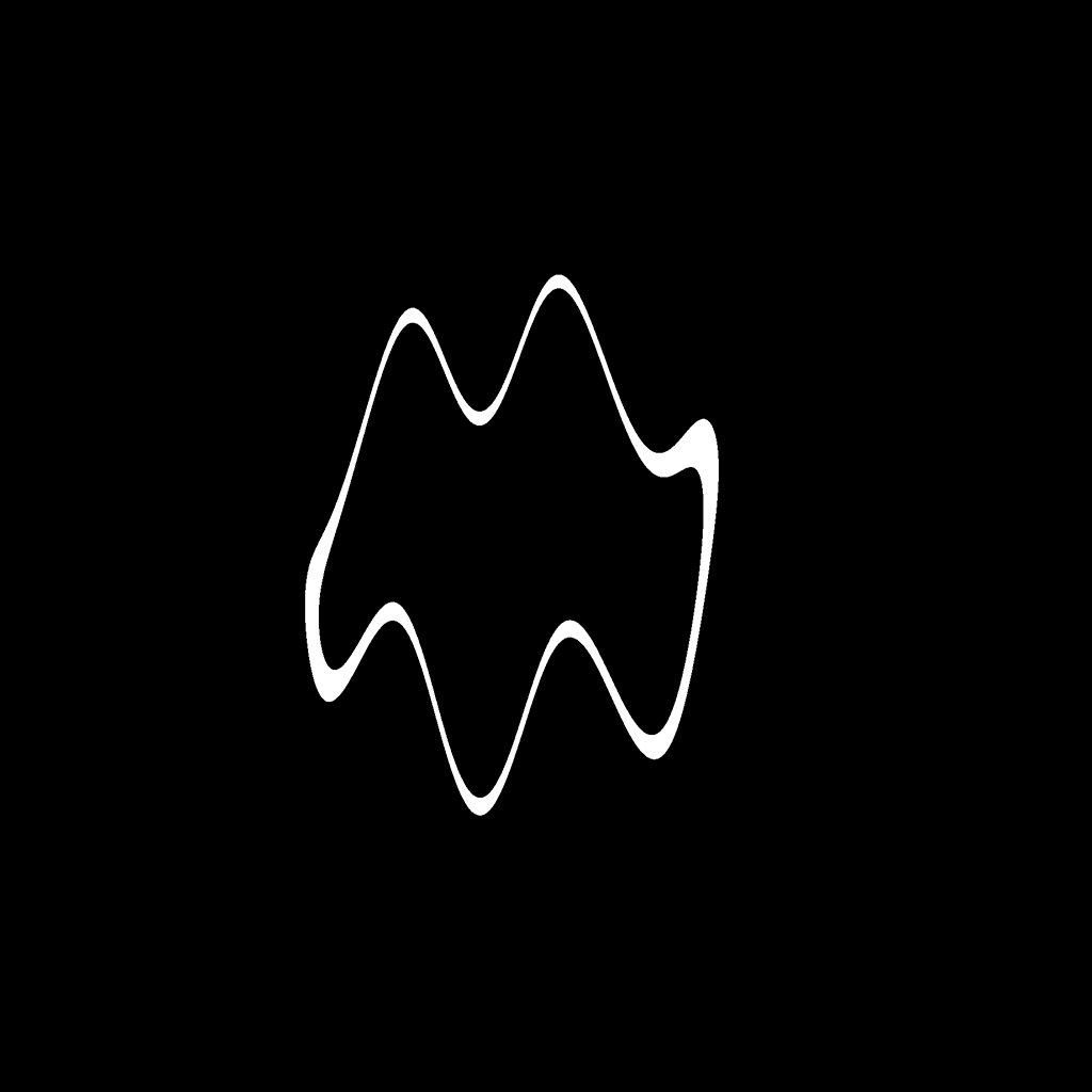
Pattern 39
And we just have to increase the sin(...) frequency to end up with a psychedelic effect:
vec2 wavedUv = vec2(
    vUv.x + sin(vUv.y * 100.0) * 0.1,
    vUv.y + sin(vUv.x * 100.0) * 0.1
);
float strength = 1.0 - step(0.01, abs(distance(wavedUv, vec2(0.5)) - 0.25));
GLSL
Copy
Imagine animating that.
Pattern 40
This pattern is actually the angle of vUv . To get an angle from 2D coordinates, we can use atan(...) :
float angle = atan(vUv.x, vUv.y);
float strength = angle;
GLSL
Copy
Pattern 41
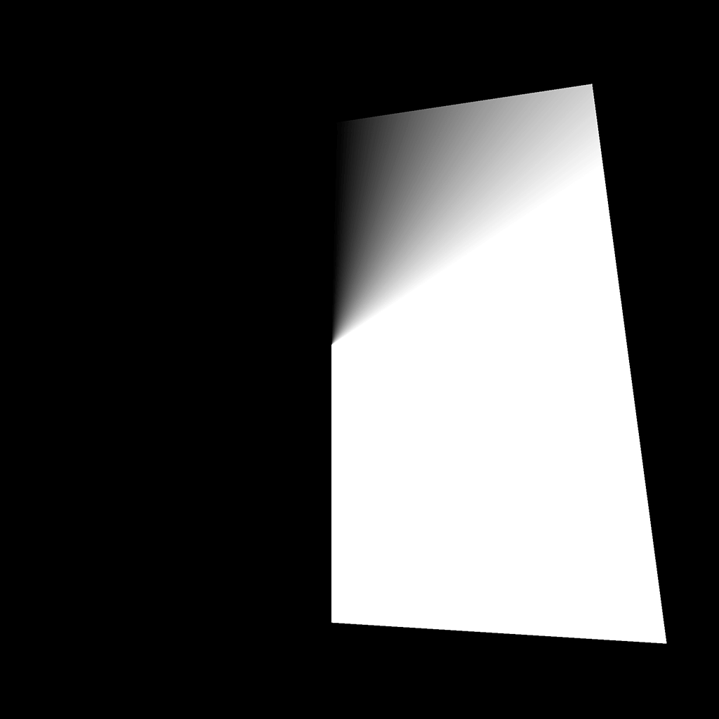
This pattern is the same but with a 0.5 offset on the vUv , to create an angle around the center:
float angle = atan(vUv.x - 0.5, vUv.y - 0.5);
float strength = angle;
GLSL
Copy
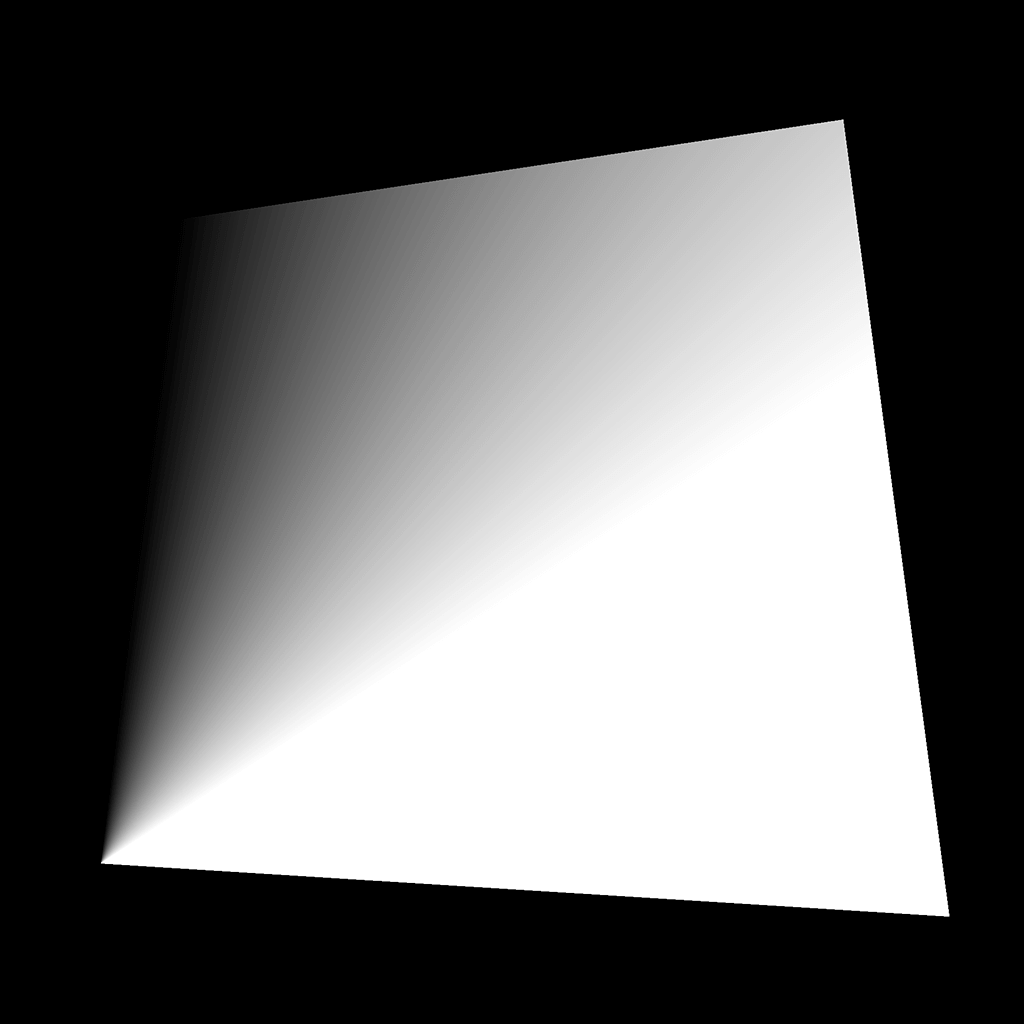
Pattern 42
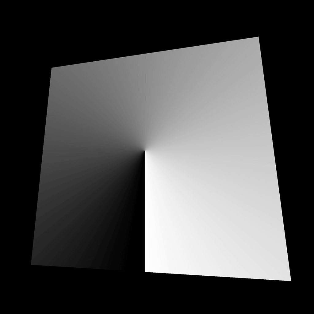
One more time, this pattern is the same, but with the angle going from 0.0 to 1.0 . Currently, atan(...) returns a value between -π and +π . First, we can divide by PI * 2 :
float angle = atan(vUv.x - 0.5, vUv.y - 0.5);
angle /= PI * 2.0;
float strength = angle;
GLSL
Copy
We get a value that goes from -0.5 to 0.5 . We just have to add 0.5 :
float angle = atan(vUv.x - 0.5, vUv.y - 0.5);
angle /= PI * 2.0;
angle += 0.5;
float strength = angle;
GLSL
Copy
Having a proper angle is a positive way to play with circular shapes. We will regroup the angle operations into one line to read it more easily:
float angle = atan(vUv.x - 0.5, vUv.y - 0.5) / (PI * 2.0) + 0.5;
GLSL
Copy
Pattern 43
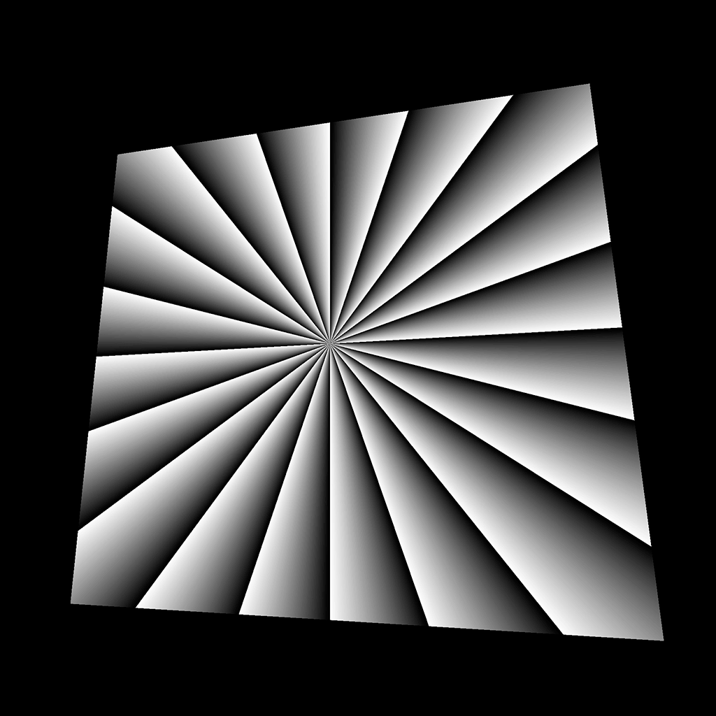
This pattern is based on the same technique we used at the beginning with modulo, but this time, with angle :
float angle = atan(vUv.x - 0.5, vUv.y - 0.5) / (PI * 2.0) + 0.5;
float strength = mod(angle * 20.0, 1.0);
GLSL
Copy
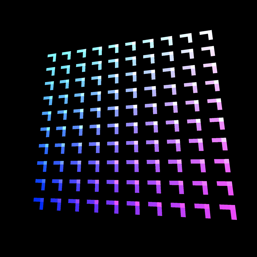
Pattern 44
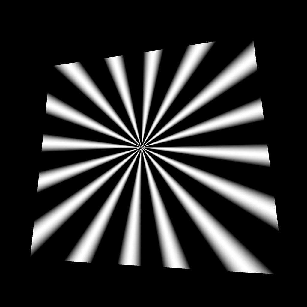
And this one is using sin(...) :
float angle = atan(vUv.x - 0.5, vUv.y - 0.5) / (PI * 2.0) + 0.5;
float strength = sin(angle * 100.0);
GLSL
Copy
Pattern 45
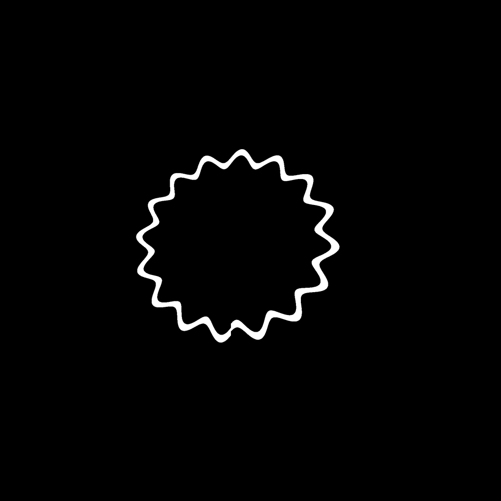
We can use the previous value to define the circle we drew earlier’s radius:
float angle = atan(vUv.x - 0.5, vUv.y - 0.5) / (PI * 2.0) + 0.5;
float radius = 0.25 + sin(angle * 100.0) * 0.02;
float strength = 1.0 - step(0.01, abs(distance(vUv, vec2(0.5)) - radius));
GLSL
Copy
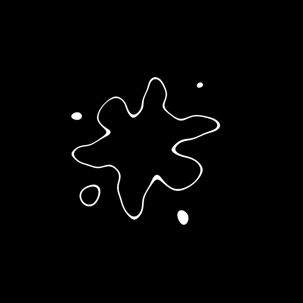
Pattern 46
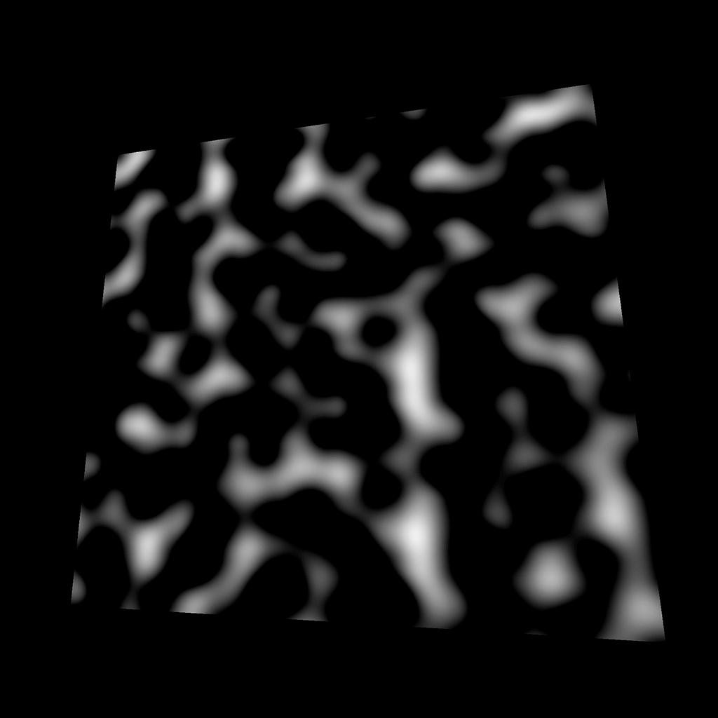
This pattern is called perlin noise. You probably already have heard of it, and, if not, you probably saw it without knowing it. The perlin noise is instrumental in recreating nature shapes like clouds, water, fire, terrain elevation but it can also be used to animate the grass or snow moving in the wind.
There are many perlin noise algorithms with different results, different dimensions (2D, 3D, and even 4D), some that repeat themselves, others more performant, etc.
Here is a Github gist that lists some of the most popular perlin noises we can find for GLSL: https://gist.github.com/patriciogonzalezvivo/670c22f3966e662d2f83
Be careful though; some codes might not work immediately as we will see. We will now test the first Classic Perlin Noise by Stefan Gustavson , which is a 2D noise —we provide a vec2 and we get a float in return. Only copy the code to your shader, but don’t use it yet:
//  Classic Perlin 2D Noise
//  by Stefan Gustavson
//
vec2 fade(vec2 t)
{
    return t*t*t*(t*(t*6.0-15.0)+10.0);
}

float cnoise(vec2 P)
{
    vec4 Pi = floor(P.xyxy) + vec4(0.0, 0.0, 1.0, 1.0);
    vec4 Pf = fract(P.xyxy) - vec4(0.0, 0.0, 1.0, 1.0);
    Pi = mod(Pi, 289.0); // To avoid truncation effects in permutation
    vec4 ix = Pi.xzxz;
    vec4 iy = Pi.yyww;
    vec4 fx = Pf.xzxz;
    vec4 fy = Pf.yyww;
    vec4 i = permute(permute(ix) + iy);
    vec4 gx = 2.0 * fract(i * 0.0243902439) - 1.0; // 1/41 = 0.024...
    vec4 gy = abs(gx) - 0.5;
    vec4 tx = floor(gx + 0.5);
    gx = gx - tx;
    vec2 g00 = vec2(gx.x,gy.x);
    vec2 g10 = vec2(gx.y,gy.y);
    vec2 g01 = vec2(gx.z,gy.z);
    vec2 g11 = vec2(gx.w,gy.w);
    vec4 norm = 1.79284291400159 - 0.85373472095314 * vec4(dot(g00, g00), dot(g01, g01), dot(g10, g10), dot(g11, g11));
    g00 *= norm.x;
    g01 *= norm.y;
    g10 *= norm.z;
    g11 *= norm.w;
    float n00 = dot(g00, vec2(fx.x, fy.x));
    float n10 = dot(g10, vec2(fx.y, fy.y));
    float n01 = dot(g01, vec2(fx.z, fy.z));
    float n11 = dot(g11, vec2(fx.w, fy.w));
    vec2 fade_xy = fade(Pf.xy);
    vec2 n_x = mix(vec2(n00, n01), vec2(n10, n11), fade_xy.x);
    float n_xy = mix(n_x.x, n_x.y, fade_xy.y);
    return 2.3 * n_xy;
}
GLSL
Copy
Unluckily, this code seems to break our shader, and it’s because a function named permute is missing. Here it is and you can add it right before the fade function:
vec4 permute(vec4 x)
{
    return mod(((x*34.0)+1.0)*x, 289.0);
}
GLSL
Copy
We now have access to a cnoise function, and we can use the vUv on it:
float strength = cnoise(vUv);
GLSL
Copy
It’s a rough result, but still, we have something. To see more of the pattern like in the preview, multiply the vUv by 10.0 :
float strength = cnoise(vUv * 10.0);
GLSL
Copy
Pattern 47
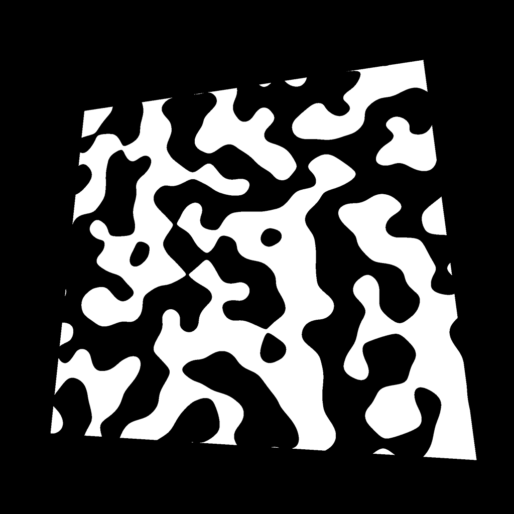
This pattern uses the same noise, but with a step on it:
float strength = step(0.0, cnoise(vUv * 10.0));
GLSL
Copy
Very useful if at some point, you feel like creating a cow.
Pattern 48

For this pattern, we used an abs(...) on the value, and subtract the result to 1.0 :
float strength = 1.0 - abs(cnoise(vUv * 10.0));
GLSL
Copy
You can work with it to create lightnings, reflection under water or plasma energy things.
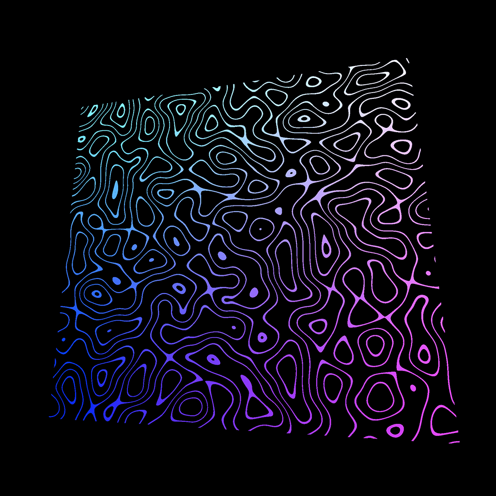
Pattern 49
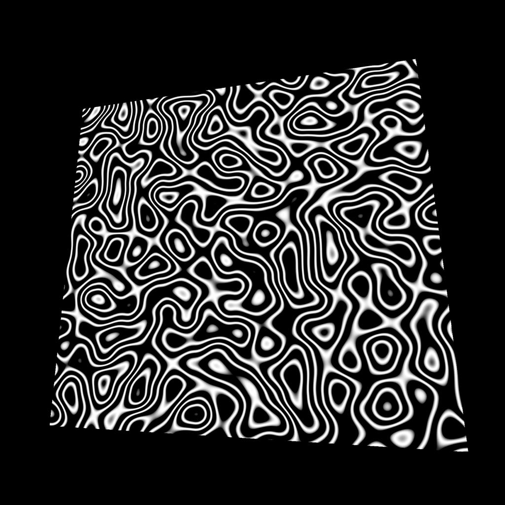
For this pattern, we applied a sin(...) on the noise:
float strength = sin(cnoise(vUv * 10.0) * 20.0);
GLSL
Copy
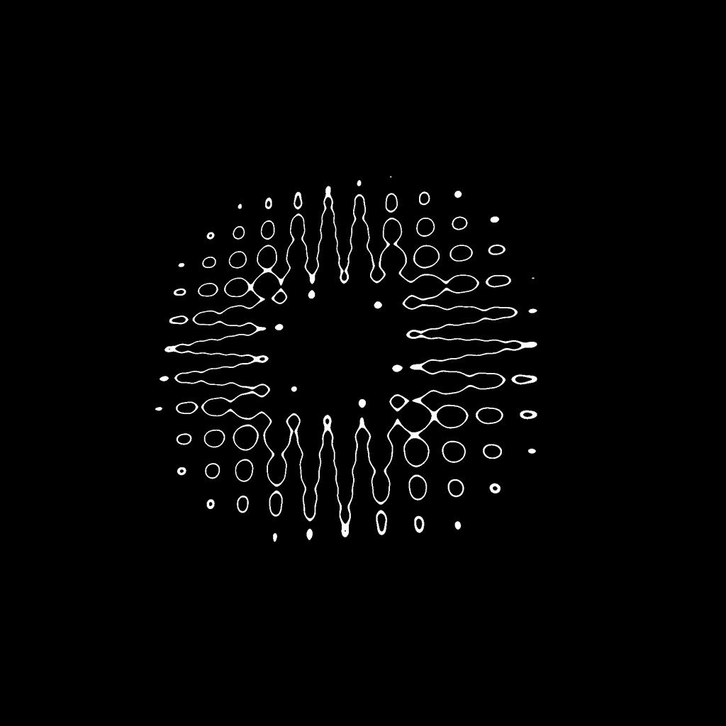
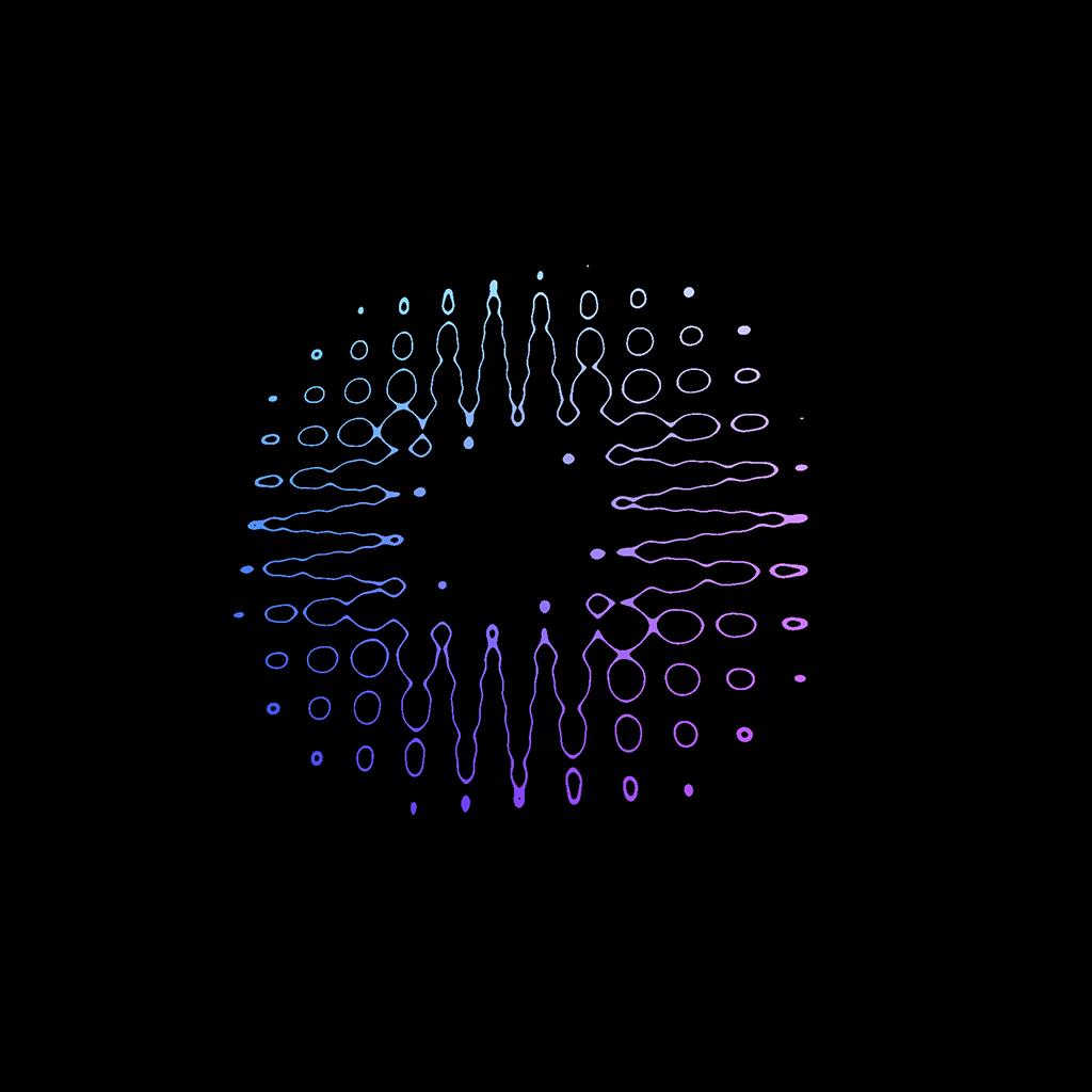
Pattern 50
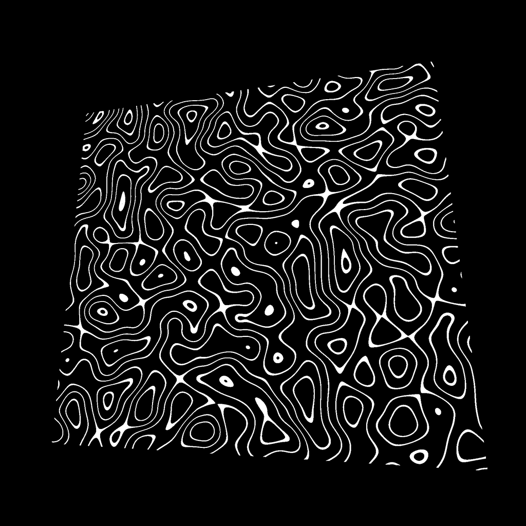
And for this final one, we combined the sin(...) and the step(...) :
float strength = step(0.9, sin(cnoise(vUv * 10.0) * 20.0));
GLSL
Copy
Easy peasy, black and white lemon squeezy.
Test it with colors
It was fun, but these black and white colors are getting dull. One cool color we had at the start was when we used the vUv directly in the gl_FragColor :
gl_FragColor = vec4(vUv, 1.0, 1.0);
GLSL
Copy
What we can do now is use that gradient color instead of the white.
Mix colors
To do this, we are going to use the mix(...) function. This function needs 3 arguments:
- A first input that can be a
float, avec2, avec3, or avec4. - A second input, which should be of the same type.
- A third value that has to be a
float. It will decide to take more of the first input or more of the second one. If we use0.0, the returned value will be the first input. If we use1.0, the return value will be the second one. If we use0.5, the value will be a mix between the two inputs. You can also go below0.0or above1.0and the values will be extrapolated.
Let’s create a first color:
vec3 blackColor = vec3(0.0);
GLSL
Copy
Let’s form a second color:
vec3 uvColor = vec3(vUv, 1.0);
GLSL
Copy
We obtain the mix between the two colors according to the strength :
vec3 mixedColor = mix(blackColor, uvColor, strength);
GLSL
Copy
And we use that mix in the gl_FragColor without changing the alpha:
gl_FragColor = vec4(mixedColor, 1.0);
GLSL
Copy
Have fun testing this with all the previous patterns.

Fix the strength
If you test patterns such as #11, #14, and #15 with this UV gradient, you’ll see some strange behaviors at the intersections.

It looks like the intersections are too bright, and that’s what they are exactly. It’s because the strength value that we use in the mix(...) is higher than 1.0 and the output gets extrapolated —meaning it goes beyond the second value.
To limit this value, we can use the clamp(...) function on the strength . This function will simply set a low and a high limits to a value:
// Pattern 11
float strength = step(0.8, mod(vUv.x * 10.0, 1.0));
strength += step(0.8, mod(vUv.y * 10.0, 1.0));
strength = clamp(strength, 0.0, 1.0);

// ...

// Pattern 14
float barX = step(0.4, mod(vUv.x * 10.0, 1.0)) * step(0.8, mod(vUv.y * 10.0, 1.0));
float barY = step(0.8, mod(vUv.x * 10.0, 1.0)) * step(0.4, mod(vUv.y * 10.0, 1.0));
float strength = barX + barY;
strength = clamp(strength, 0.0, 1.0);

// Pattern 15
float barX = step(0.4, mod(vUv.x * 10.0 - 0.2, 1.0)) * step(0.8, mod(vUv.y * 10.0, 1.0));
float barY = step(0.8, mod(vUv.x * 10.0, 1.0)) * step(0.4, mod(vUv.y * 10.0 - 0.2, 1.0));
float strength = barX + barY;
strength = clamp(strength, 0.0, 1.0);
GLSL
Copy


Go further
There are many other potential patterns and many additional functions. The idea of this lesson was to give you strings to your bow for your future projects and to practice GLSL in a trivial context.
One useful thing we didn’t try would be to put those shapes into functions. We could have created a getCircle function, a getSquare function, etc. with correct parameters to reuse them easily.
Keep practicing, don’t be afraid to create new shapes, experiment, and look for help if you need it.
Also, try to add some uniforms to animate the values or add some tweaks to the debug panel.