22 Custom model with Blender
Difficulty Hard
Introduction
Now that we know how to import a model into our scene; let’s learn how to create our own model using a 3D software.
Choosing a software
There are many software like Cinema 4D, Maya, 3DS Max, Blender, ZBrush, Marmoset Toolbag, Substance Painter, etc. These are great, and they differ on divers criteria like the UX, the performance, the features, the compatibility, the price, etc.
In this lesson, we are going to use Blender because it’s free, the performances are remarkable, it works with all primary OS, it has many features, it has a vast community, and it became a lot easier since the 2.8 version.
Be aware that you won’t be a Blender expert at the end of the lesson. It would take a full course to learn all its aspects, and they are already many great resources to learn. The idea is to understand the basics and de-mystify the software to have sufficient baggage to create simple models.
At the start, we will discover all the basics. That will be a lot to take in but don’t worry; we will repeat most of the shortcuts, the mechanics, and the features multiple times.
If you pressed a wrong shortcut at some point, you lost your scene, or the interface is completely messed up, just close and re-open Blender.
Downloading Blender
Go to the blender website download page and download the latest version: https://www.blender.org/download/
The software is pretty light, and it shouldn’t take more than a few minutes.
Once downloaded, simply install it.
The lesson has been written and recorded with Blender 2.83.5 . While there shouldn’t be major differences, keep an eye on potential changes.
Interface
Splash screen
The splash screen gives you access to some useful links, templates, and recently opened files.
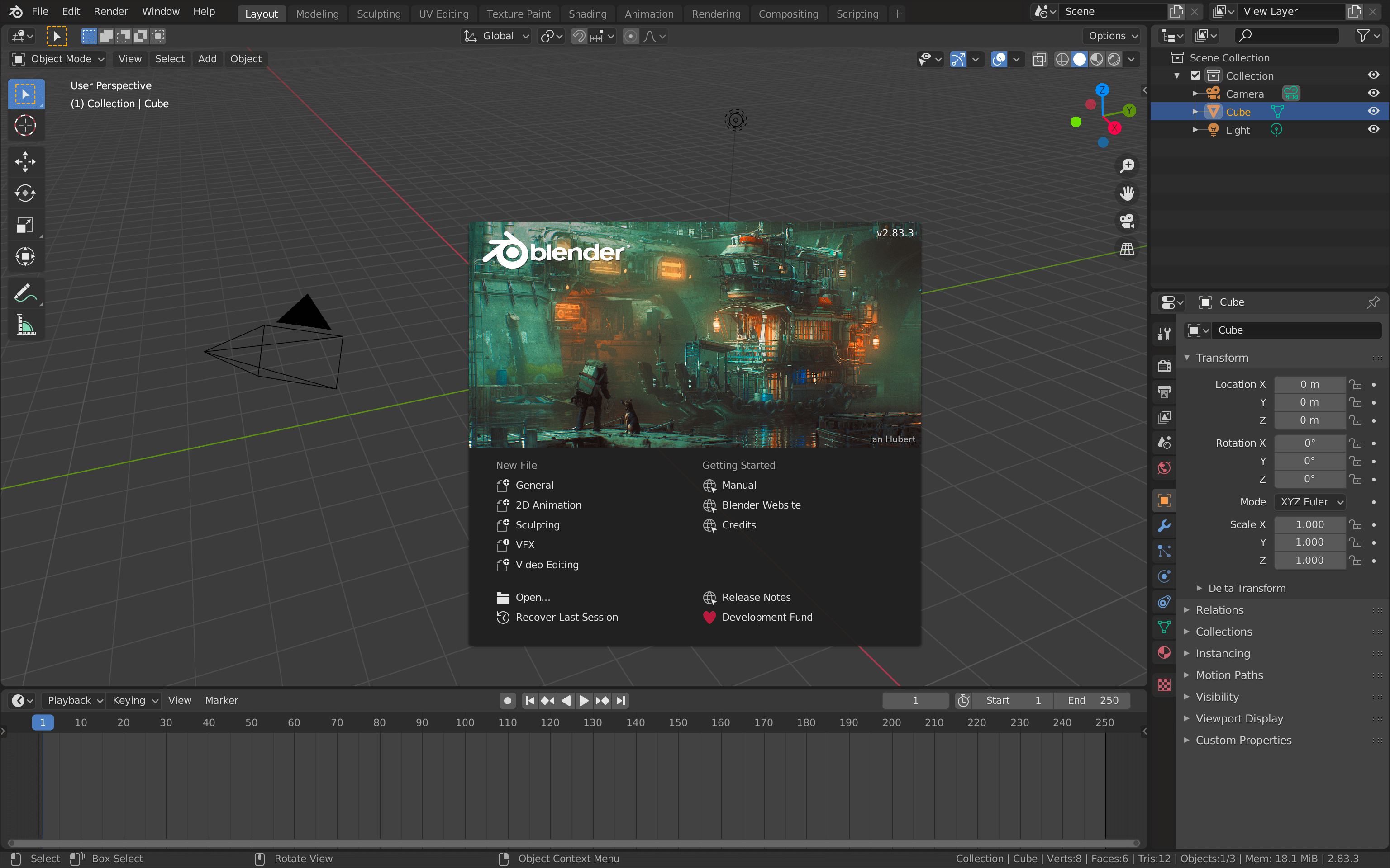
The image changes with the Blender version, so don’t be surprised if you have a different one.
You can also see the exact version on the top right of it.
Click anywhere out of the splash screen to close it.
Areas
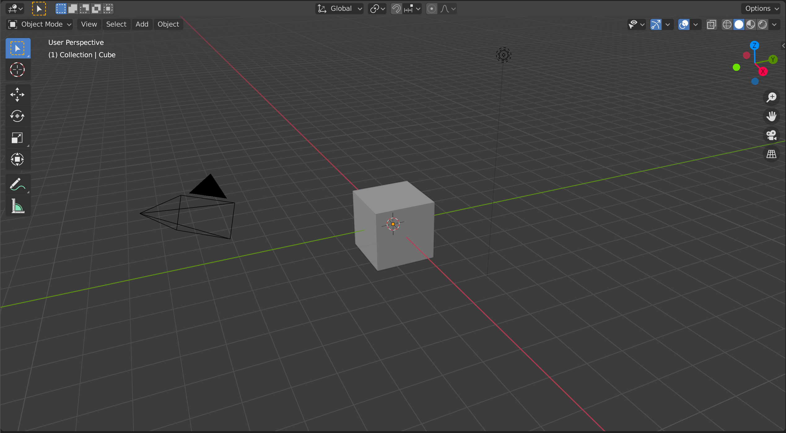
The different parts of the interface are called areas. Areas are very flexible, and you can create the layout that you want.
Default areas
By default, you have the main area called the 3D Viewport :
The Timeline to create animations:

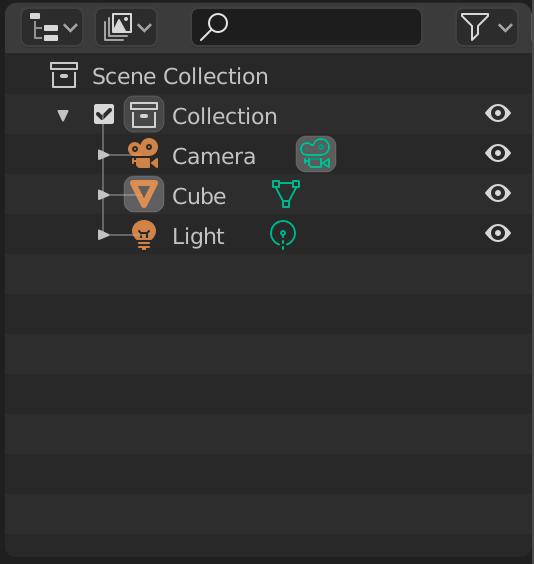
The Outliner to see and manage the scene graph (or scene tree):
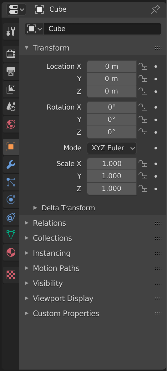
The Properties to manage the properties of the active object (selection) and the environment:
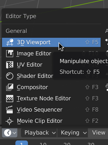
Change an area
To change what an area is displaying, click on the top-left button of that area. Here, we are going to change the Timeline area.
We are going to change the Timeline area for another 3D Viewport :
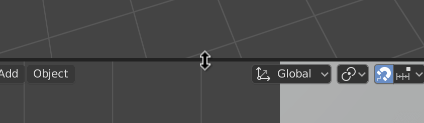
Resize an area
To resize an area, position your cursor between two areas and drag & drop:
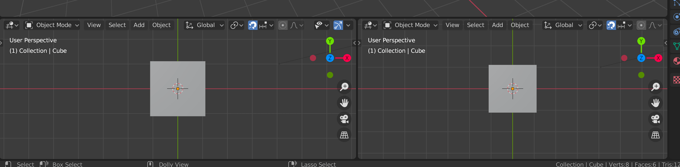
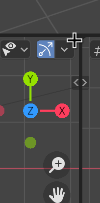
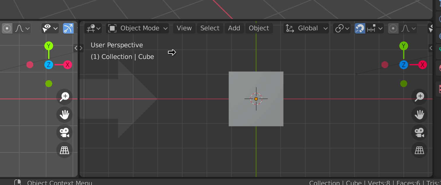
Create new areas
To create a new area, first, we must decide what area we want to split. Then, we must position our cursor in one of the four corners of our area (a few pixels inside the area):
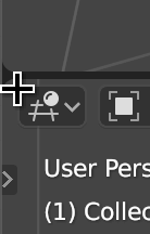
Finally, we drag and drop in the area we want to split:
Remove an area
Removing an area is a little tricky, and you might end up with dozens of unwanted areas. Don’t worry, once you get the idea, it will be fine.
In a way, we don’t remove an area; we un-split two areas. First, you must decide which one of the two areas is going to take over the other. If you want to remove the right area, start from the left area. Then place your cursor in one of the two corners adjacent to the area we want to remove (few pixels inside the area that is supposed to take over the other):
And then drag & drop (just like we did to create an area) but this time in the opposite direction (toward the area we want to remove):
It can take a few tries but you’ll get it.
Shortcuts
One of the strengths of Blender is its shortcuts. There are tons of them, and once you master the basics, you can be very efficient. Don’t worry; you can use all the shortcut actions through the interface or with the search panel that we will see later. Throughout this lesson, we will discover some of the more critical shortcuts.
Here’s a non-exhaustive list of shortcuts: https://docs.google.com/document/d/1wZzJrEgNye2ZQqwe8oBh54AXwF5cYIe56EGFe2bb0QU/edit?usp=sharing
One important thing to understand is that shortcuts are hovered area sensitive. That means that the same shortcut can have different actions depending on what’s behind our cursor. Most of the shortcuts we will see in this lesson concern the 3D Viewport . You should always make sure to keep your cursor above one of these areas when pressing the shortcut keys.
The shortcuts are also mode sensitive, but we will talk about modes later.
Only one or two shortcuts that we will see are different between Mac and Windows. If there is a difference, both versions will be cited. If the shortcut includes the CTRL key and you are using a Mac, do not assume it’s CMD . Use the CTRL key instead.
View
As you can see, you can move the view in every possible direction. While you can use a trackpad, I recommend using a mouse with a wheel that you can press (or a third button) for productive reasons. From now, we will refer to the wheel button (the one that we can press) as MIDDLE MOUSE .
If you are using a trackpad, you can use two fingers.
If you are using a Magic Mouse, you can replicate the MIDDLE MOUSE . Go to the preferences through Edit > Preferences . Using the navigation menu on left, choose the Input section. Check the Emulate 3 Button Mouse checkbox.
It’s also better to have a numeric pad.
Orbit rotate
We can rotate the view by pressing the MIDDLE MOUSE and drag & drop in the 3D Viewport .
Or we can use the gizmo on the top-right part of each 3D Viewport :
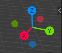
We call this rotation orbit (like the Three.js OrbitControl) because the view rotates around an invisible center called view-point. We will talk about that point later.
Truck and pedestal
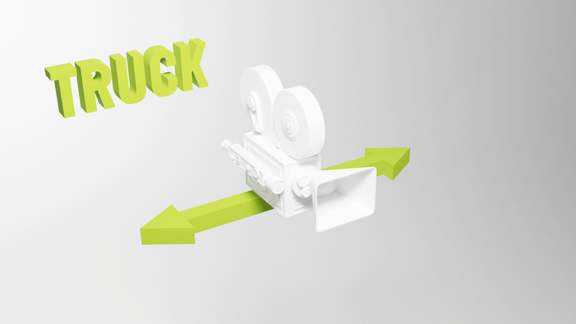
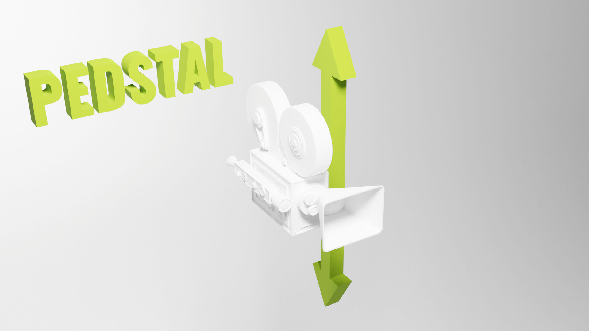
Truck is when the view moves on the left and right, while pedestal is when the view moves up and down. We can do both simultaneously by pressing the MIDDLE MOUSE again, but this time with the SHIFT key pressed.
Or we can use the hand icon on the top right:

Truck is also called track.
Some might also wrongly call those movements “pan”.
Dolly
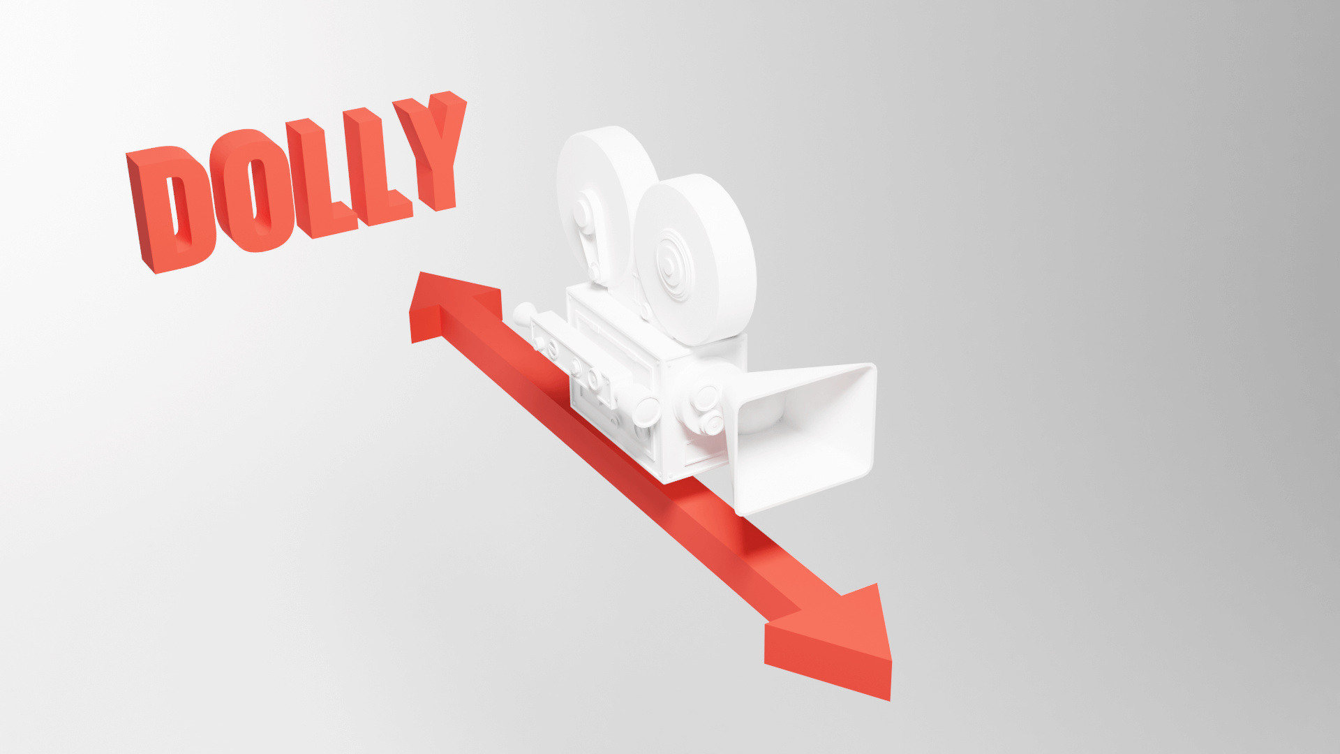
Dolly is when the view moves forward and backward. We can use the WHEEL to achieve that.
Or we can use the magnifier icon on the top right:

Be careful though; zooming isn’t exactly like going forward and backward. We are getting closer or further from the view-point we talked about in the Orbit section, but we cannot zoom beyond that point, and zooming too much will result in a stuck view.
To resolve this zoom limit issue, we can move forward and backward by pressing SHIFT + CTRL + MIDDLE MOUSE and drag & drop in the 3D Viewport (won’t work with the two fingers technique with a trackpad). This way, we won’t get stuck at the view-point.
There is no icon in the interface to do that.
Tilt and pan


Tilt and pan are simple rotation on the camera point.
We have to go to the Walk mode —also called Fly mode— to use those moves.
To do that, if you are using a QWERTY keyboard, press SHIFT + BACK QUOTE . The back quote —also called backtick, acute or left quote— is an inclined simple quote that can be used to add a grave accent.
Finding that character might be a little hard because its position changes a lot depending on your keyboard. You can find it on the top right corner, on the bottom left corner or very close to the ENTER key.
If you are using an AZERTY keyboard, the shortcut won’t work. We need to change the keymap. Go to the preferences through Edit > Preferences . Using the navigation menu on left, choose the Keymap section. In the search input, write view navigation and change the shortcut for View Navigation (Walk/Fly) to SHIFT + F .
That’s it, you can use the walk mode with SHIFT + F .
You can also go forward, backward, and on the sides, in the walk mode with the ARROWS or WASD if using a QWERTY .
Perspective / Orthographic
The default view uses perspective. We can toggle with the orthographic version with NUMPAD 5 or the grid icon on the top right:

Axes
We can align the camera on the X , Y and Z axes by pressing the NUMPAD 1 , NUMPAD 3 , and NUMPAD 7 . We are talking about the numeric pad numbers, not the numbers at the top of the keyboard.
To position the camera at the opposite, press the same keys but with CTRL .
Or we can use the gizmo and click on the axes:
In Blender, we consider the top axes as the Z , unlike in Three.js, where it’s Y .
Camera
You might have seen the camera in the 3D Viewport . To get the camera viewpoint, press NUMPAD 0 :

The camera will be used when doing renders. You can’t render the scene without a camera.
Reset
Sometimes, we get lost, and we don’t even know where our scene is. We can focus back on our scene by pressing SHIFT + C .
Focus
To focus the camera on an object, select the object with LEFT MOUSE , then press NUMPAD , (we are talking about the comma on the numeric pad and it might be a dot depending on the keyboard you are using).
We can also focus on an object and hide everything else with NUMPAD / . Use the same shortcut to leave the focus mode.
Selecting
As we just saw, we can select objects with the LEFT MOUSE . We can also select multiple objects with SHIFT + LEFT MOUSE .
You might have noticed that one of the objects always has a brighter outline. This object isn’t just selected; it’s also the active one. We will see more about that later.
To undo a selection, press CMD + Z ( CTRL + Z on Windows). Yes, selecting objects is considered as an action we can undo. While this might seem strange, it’s really helpful when you miss-click.
To unselect an object, use SHIFT + LEFT MOUSE again. If it’s not the active one, it’ll become active, and if it’s active, it’ll be unselected.
To select everything, press A .
To unselect everything, double press A .
To select a rectangle area, press B .
To select like if you were painting, press C . While in this mode, use WHEEL to change the radius.
Creating objects
To create objects, with the cursor above a 3D Viewport , press SHIFT + A . A menu should open behind your cursor. Navigate through this menu to create various objects. Most of what we will see in the lessons are in the Mesh sub-menu:

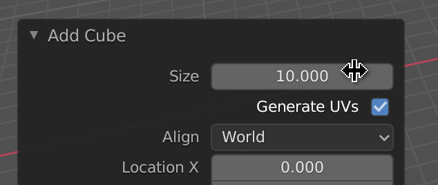
When you create an object, a small button should appear in the bottom left corner:
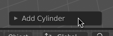
Click on it to change various properties like the size, the subdivision, and many other properties related to the object you’re trying to make:
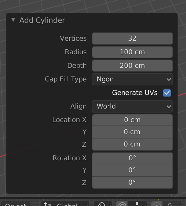
If you click anywhere else, you’ll lose that menu. You can re-open it with F9 but if you start doing modifications on the geometry, you won’t be able to re-open this menu.
Deleting objects
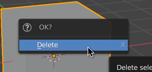
To delete an object, select it and, with the cursor above a 3D Viewport , press X . A confirmation menu should open behind the cursor. Click on it to delete the object:
Hiding objects
To hide selected objects, press H .
To show hidden objects, press ALT + H .
To hide non-selected objects, press SHIFT + H .
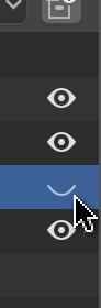
You can also manage this in the Outliner with the eye icon.
Transforming objects
There are 3 types of transformations —as in Three.js. We can change the position, the rotation, and the scale.
We can use the menu on the left to activate each separately or activate them even all together with the fourth button:
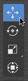
Or we can use shortcuts:
-
Gfor the position -
Rfor the rotation -
Sfor the scale
After activating one of these shortcuts, you can force the transformation to operate in a specific axis by pressing the corresponding key ( X , Y , and Z ).
Modes
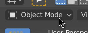
We are currently in Object Mode , where we can create, delete, and transform objects. There are many other modes.
Change mode
We can change the mode with the menu on the top-left select button of any 3D Viewport area:
Or we can press CTRL + TAB to open a wheel menu (aka, the coolest kind of menu):
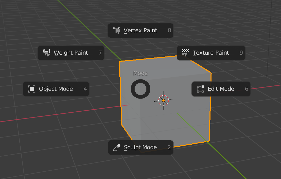
We won’t cover all the modes, but we are going to use the Edit Mode . Select a mesh (or create one) and switch to the Edit Mode .
Edit Mode
There is actually a shortcut to toggle the Edit Mode . Simply press TAB .
The Edit Mode is very similar to the Object Mode but we can edit the vertices, the edges and the faces. By default, we can change the vertex. Try to select vertices, transform them with the usual shortcuts — G for position, R for rotation, S for scale.
To switch to edges and faces, we can use the buttons on the top-right part of the 3D Viewport :
Or we can press the first three numbers on top of the keyboard 1 , 2 , and 3 .
Once you finish editing the object, leave the Edit Mode with TAB .
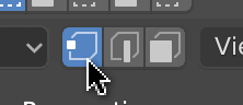
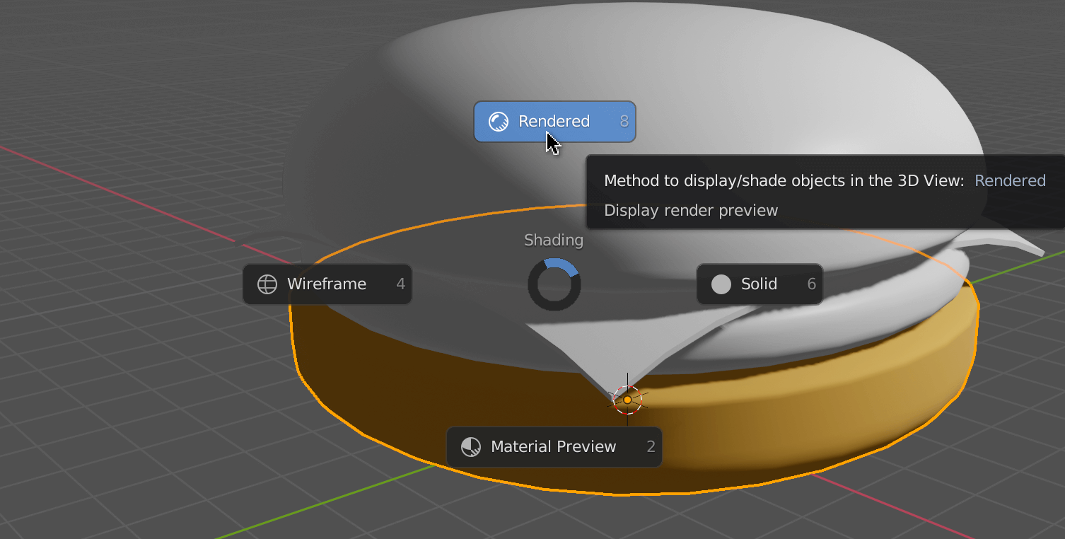
Shading
Shading is how you see objects in the 3D Viewport .
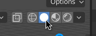
We are currently in Solid shading. This shading lets you see the objects with a default material and no light support. It’s performant and convenient.
We can change the shading with the buttons on the top-right corner of the 3D Viewport :
Or we can press Z to open a wheel menu:
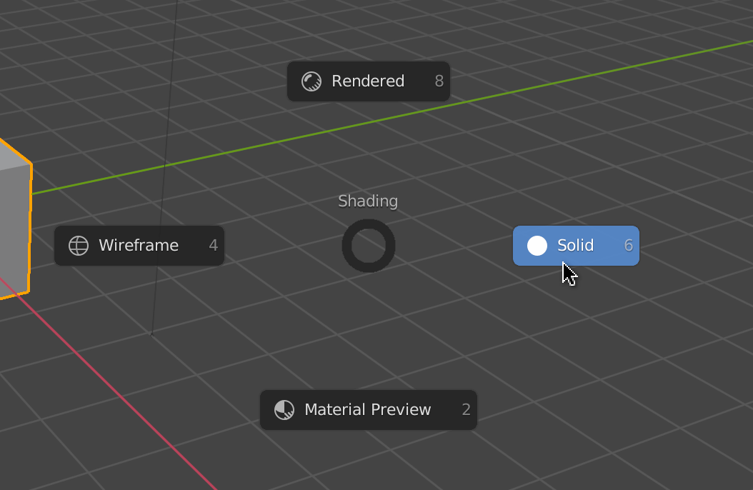
-
Solid: The default with the same material for every objects. -
Material: Like theSolidshading, but with a preview of the materials and their textures. -
Wireframe: All the geometries are in wireframe. -
Renderer: Low quality render —it’s the most realistic but the least performant.
If you can’t see much in the Render , it might be because you don’t have enough lights in your scene. Just add one or two by pressing SHIFT + A to open the Add menu.
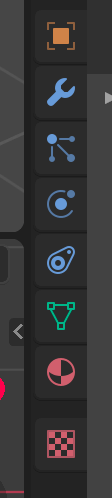
Properties
Unless you changed the layout, the bottom right area, named Properties , lets you play with render properties, environment properties and the active object’s properties. Remember that the active object is the one with the brightest outline.
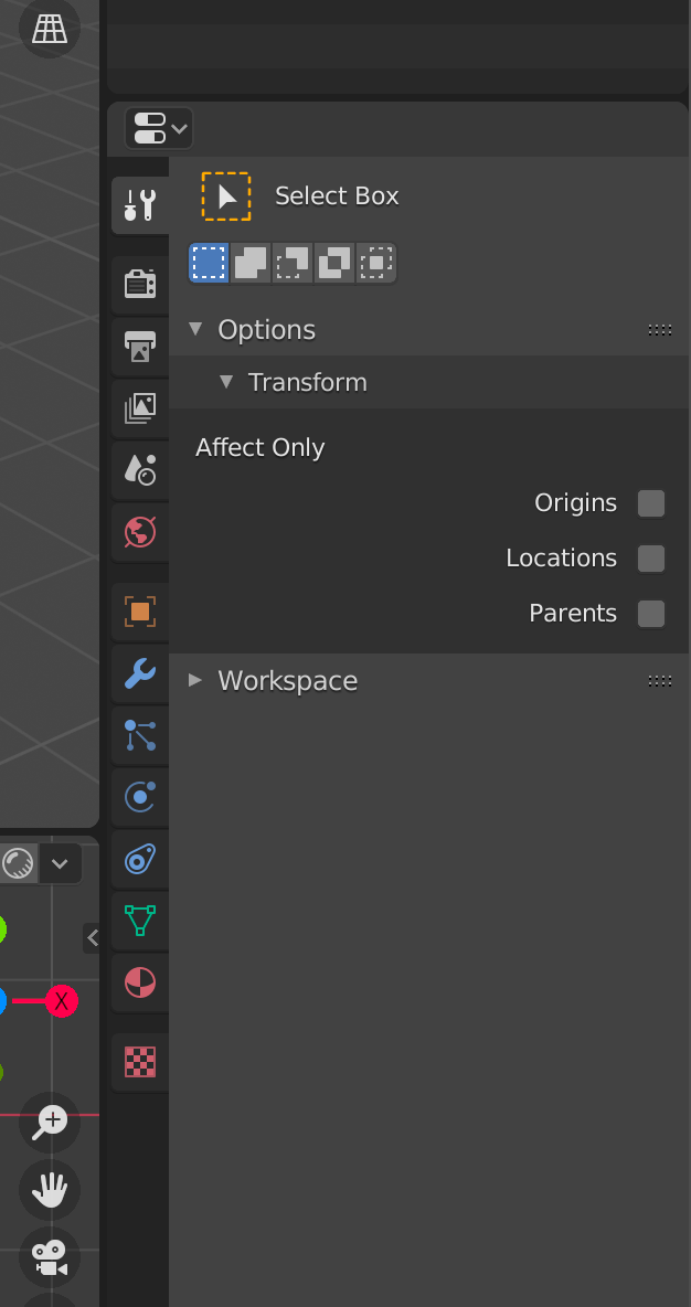
We won’t cover all these tabs but the top ones deal with the renders and the environment:
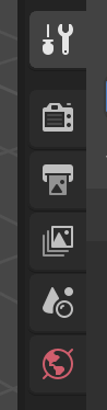
The ones below relate to the active object, and they can differ depending on the type of active object because we don’t have the same properties for a cube as for a light:
Object Properties
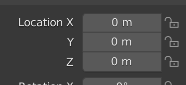
The Object Properties let you change with accuracy properties such as transformations:
Modifier Properties
The Modifiers Properties let you add what we call modifiers. These are non-destructive modifications. You can subdivide, bend, grow, shrink, etc. and turn them off as you please:

Material Properties
The Material Properties let you play with materials:

By default, you have access to one material named Material , and it should be applied to the default cube if you didn’t delete it:
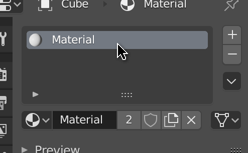
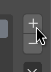
You can remove the material with the - button and combine them with the + button, but we usually use only one material per mesh:
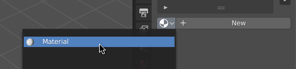
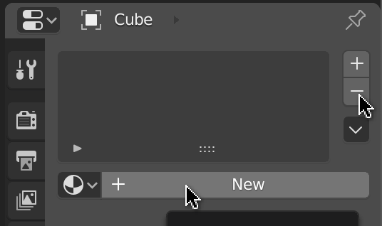
If there is no material on the mesh, we can choose an existing one, or we can create a new one with the New button:
We can have different types of surfaces for one material. The default one is called Principled BSDF and this type of surface uses the PBR principles as the MeshStandardMaterial does in Three.js. This means that we should get a very similar result if we export this kind of material to a Three.js scene.
We won’t see other types of materials in this lesson.
Render engines
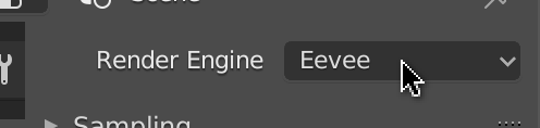
Go to the Render Properties tab:

In this panel, we can change the Render Engine :
There are 3 types of render engine:
-
Eevee: A real-time render engine. It uses the GPU just like Three.js, it’s very performant, but it has limitations like realism, light bounce, reflection, and refraction. -
Workbench: A legacy render engine that we don’t use a lot anymore. Its performance is pretty good, but the result isn’t very realistic. -
Cycles: A raytracing engine. It’s very realistic. It handles light bounce, deep reflection, deep refraction, and many other features, but it’s very sluggish, and you might end up waiting hours or even days to render your scene.
You can change this property and see if anything changes in the scene. Make sure to use the Renderer shading —press Z to change the shading. Blender developers did an excellent job of keeping a very similar result between render engines.
The default one is Eevee and it’s perfect in our case because it’s real-time rendering, and Three.js is also real-time rendering.
If you want to render the scene, press F12 . The render will be seen from the camera —make sure to have a camera well oriented in your scene.

Search
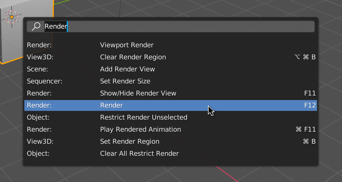
There are so many possible actions that we cannot remember how to trigger them all. The right solution when we can’t figure out where the button is, or the shortcut is to use the Search panel.
To open the Search panel, press F3 (you might need to add the fn key depending on your keyboard and OS) and write the action name:
Save our setup
Create a solid setup. It’s up to you, but because we are using Blender to export for Three.js, we don’t need a camera. We can also create two side views below the main 3D Viewport on the Z and Y axis with Wireframe shading:

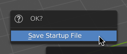
Once you’re happy with your setup, go to File > Defaults > Save Startup File . That will set your current setup as the default one when opening Blender:
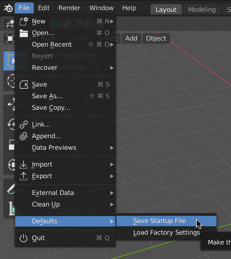
Be careful when clicking on Save Startup File ; a confirmation menu should open and if you move the mouse out of it, you’ll lose it. Click again to confirm:
Hamburger time
It’s time to create our own model. In this lesson, we are going to make a hamburger and import it into Three.js.
Like in Three.js, a good practice is to decide on a unit scale. If you look at the grid, one square truly represents one unit, and by default, Blender considers that one unit means one meter:
We could create a giant hamburger, but sorry, we better start with a regular-sized sandwich. We could just think of 1m as 1cm but if you don’t like seeing this m you can remove it in the Scene Properties tab of the Properties area by choosing None as our Unit System :
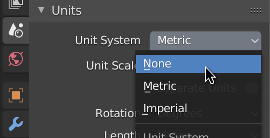
We can now consider 1 as 1cm .
Bottom bun
For our bottom bun, as strange as it may sound, we will start with a 10cm cube:
Then, after making sure that our cube is active, go to the Modifier Properties tab and add the Subdivision Surface modifier:
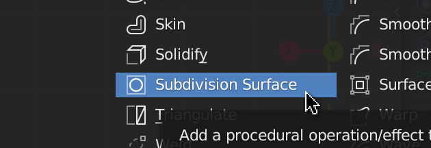
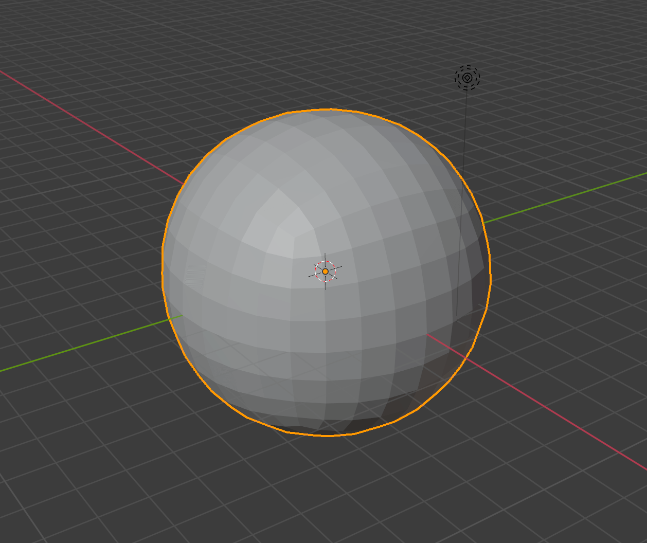
The cube now somewhat resembles a sphere.
The Subdivision Surface is one of the most famous modifiers. It subdivides the geometry but smoothes the angles at the same time.
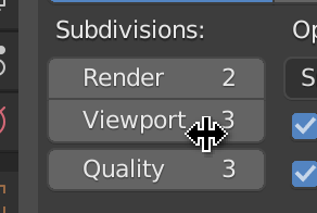
Add more subdivision in the Subdivisions > viewport field:
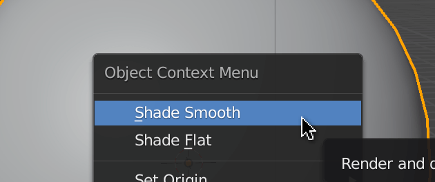
The faces are flat but we want a smooth surface. To achieve this, right-click on the sphere and choose Shade Smooth :
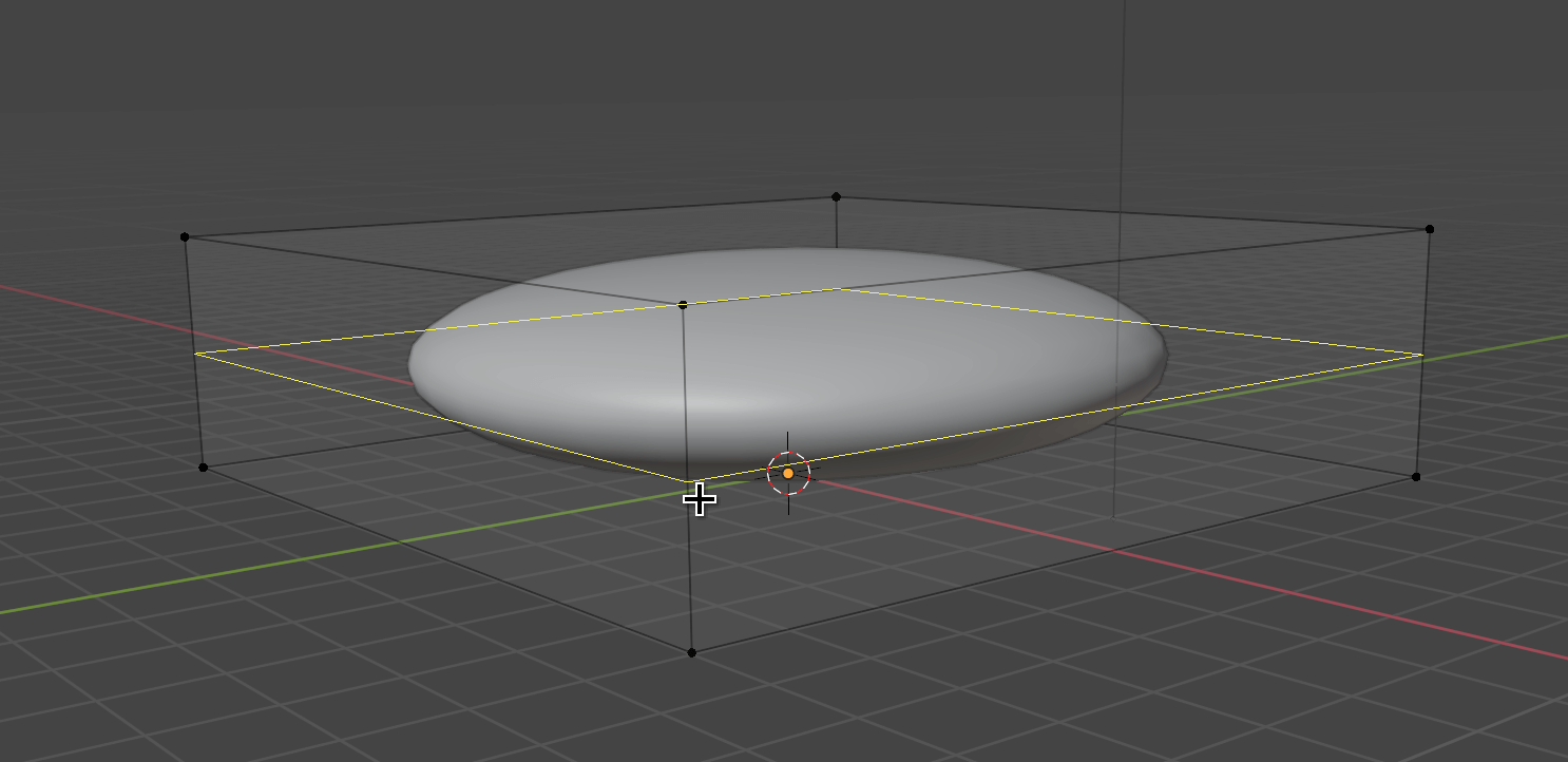
The good thing with modifiers is that you preserve the original geometry. Go to the Edit Mode by pressing TAB and move the vertices until you get a pebble right above the ground:
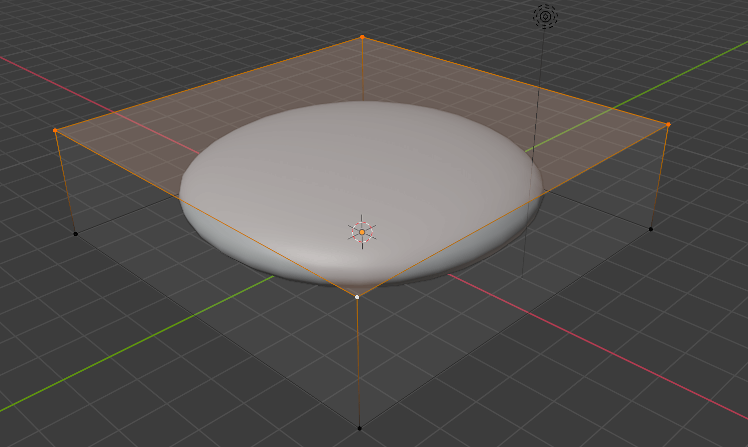
So it’s still not a bun. To get the right shape, we must add more vertices at the edge of the bun. What we need is a loop cut. Press CTRL + R while in Edit Mode and move the mouse on one of the four vertical edges:
Click once to create the cut but do not click again. At this point, you can move the loop cut up and down. Put the loop cut closer to the top edge:
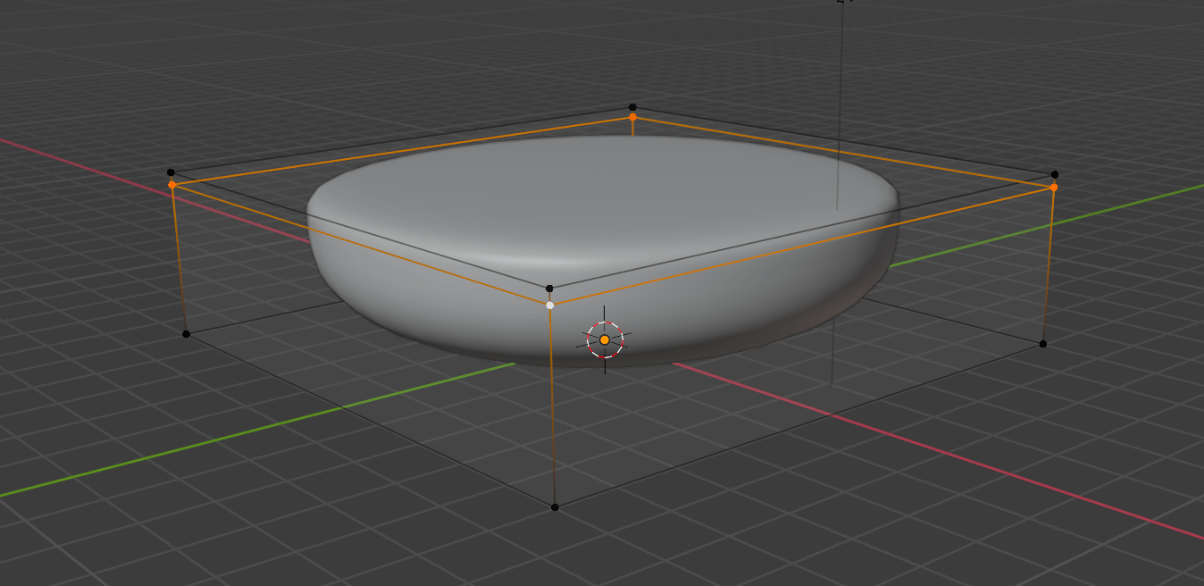
Repeat the process for the down part of the bun. We want our bun to be flat at the bottom, but not too flat:

Improve your bun until you are satisfied but don’t spend too much time on it. Don’t worry, we’ll come back to it once we have the whole scene.
Save
It’s time to save. Press CMD + S ( CTRL + S on Windows) or go to Files > Save :
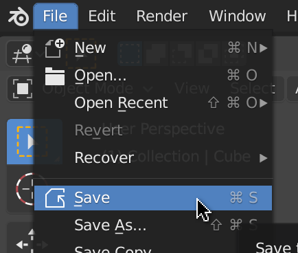
Save anywhere you want.
If you make some changes and you save again, you’ll see a .blend1 file in the same folder as your original .blend file. That is a backup of the latest save automatically generated by Blender. There was a time where Blender wasn’t as stable as it is today. Saving your file could result in corrupting it. That is why they created those automatic backups. Today, Blender is very stable, but they keep the backup just in case or because the user can make a mistake like deleting an object, saving, and closing Blender. Fortunately, you only need to rename the .blend1 file .blend to access your previous save.
Meat
Repeat the same process for the meat. You can also duplicate the bottom bun with SHIFT + D in Object Mode (the default one)
Don’t forget to save.
Cheese
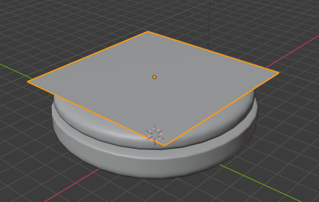
For the cheese, start with a plane right above the meat:
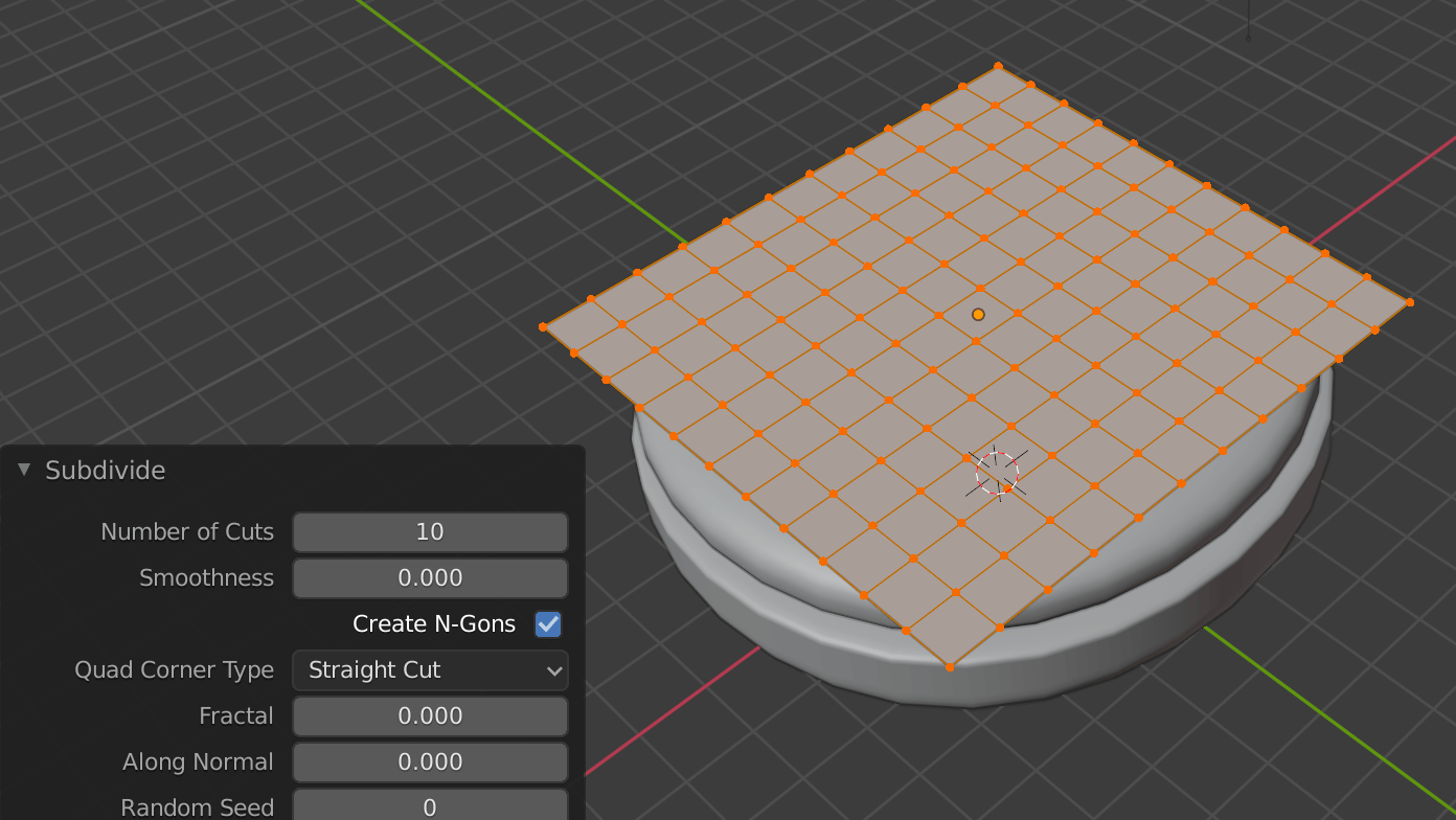
Go to Edit Mode (where you can edit the vertices, edges and faces) and subdivide the geometry. Select the only face, right click on it and select Subdivide . Set the Number of Cuts to 10 :
We are going to melt the cheese corners.
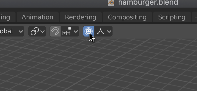
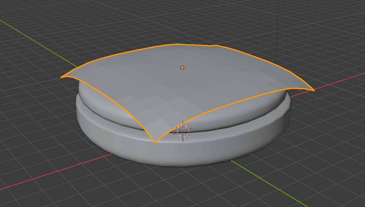
While we’re still in Edit Mode , select one of the cheese corners. If we were to move one vertex at a time, it would take too long, and the result would probably look disappointing. What we can do is use the Proportional Editing . Press O —the letter— or click on the icon at the 3D Viewport top center:
Now that the Proportional Editing is active, transforming one vertex will also transform the neighbor vertices. Increase the area of effect by using the WHEEL after pressing a transformation key —like G to move:

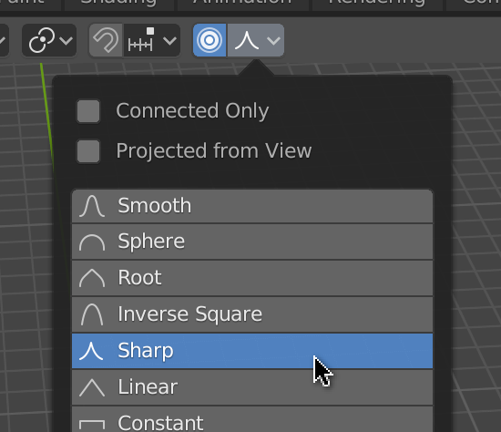
The way the neighbor vertices move isn’t correct. To change that click on the Proportional Editing Falloff icon and choose Sharp :
Now play with the vertices and the Proportional Editing size until you get a nice cheesy shape:
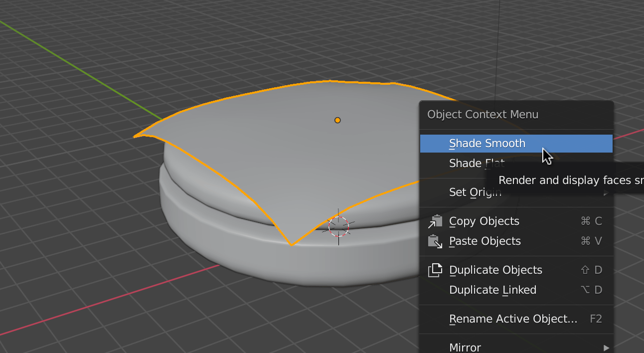
In Object Mode , right click and choose Shade Smooth for a smooth surface:
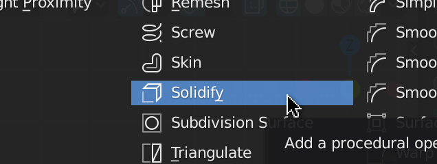
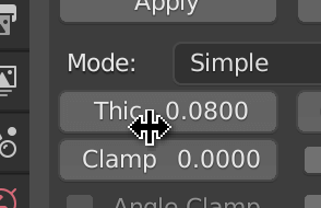
Our cheese doesn’t look thick enough. To solve this, go to the Modifier Properties and add the Solidify modifier:
Then increase the thickness to 0.08 :
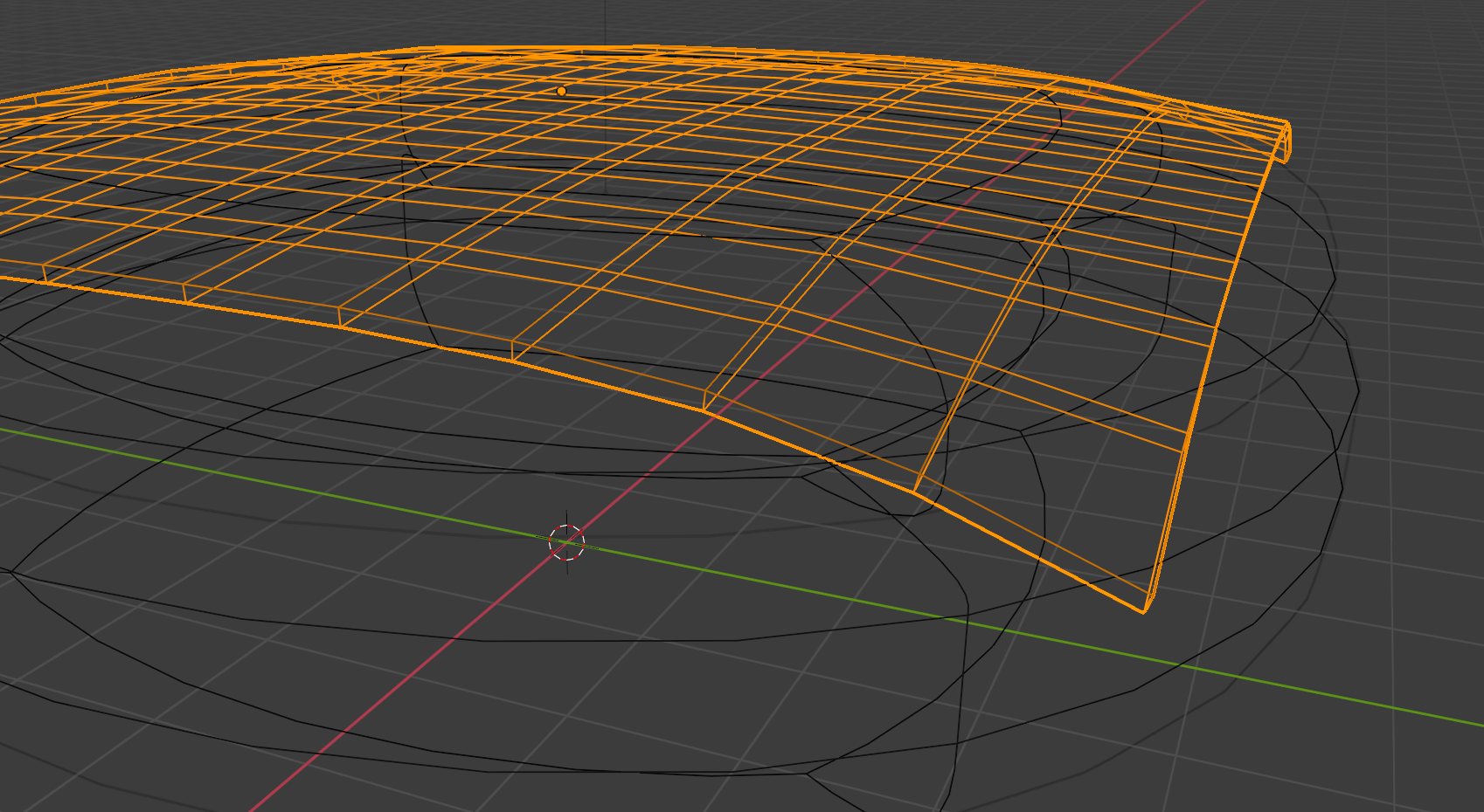
Change the shading to wireframe if you want to appreciate the result even more —press Z to open the shading wheel menu:
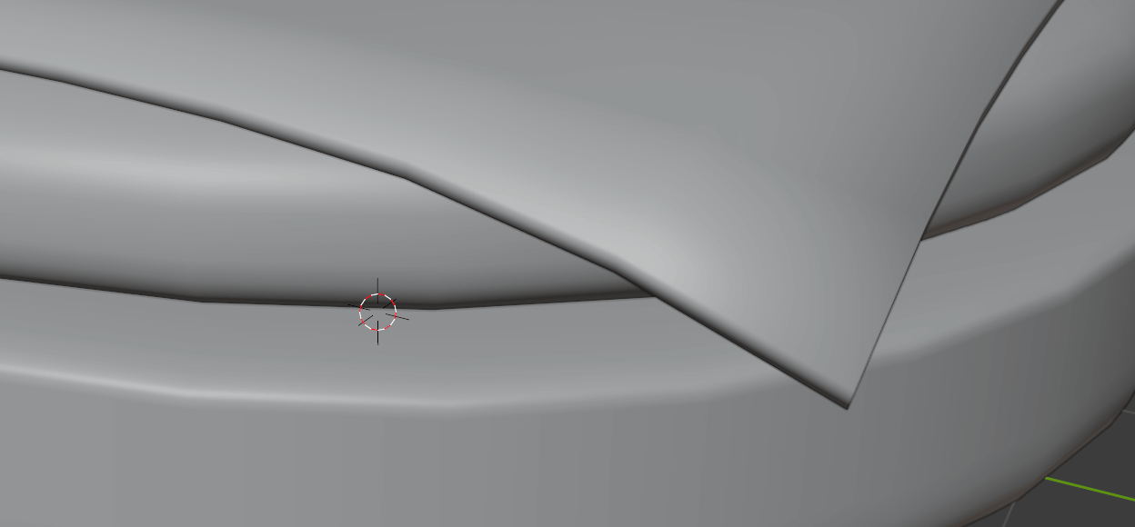
Not to sound too picky but, the Shade Smooth on the edges looks kind of strange:
To fix that, go to the Object Data Properties panel, then the Normals section, and check Auto Smooth :
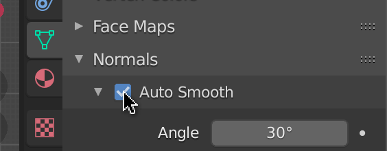
This feature will smooth the surface only if its edge’s angle is inferior to 30°. At that point, you should get a realistic and appetizing melted cheese:

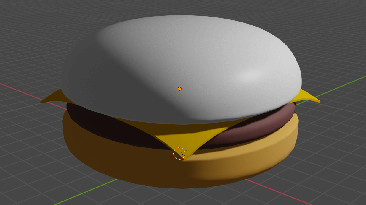
Top bun
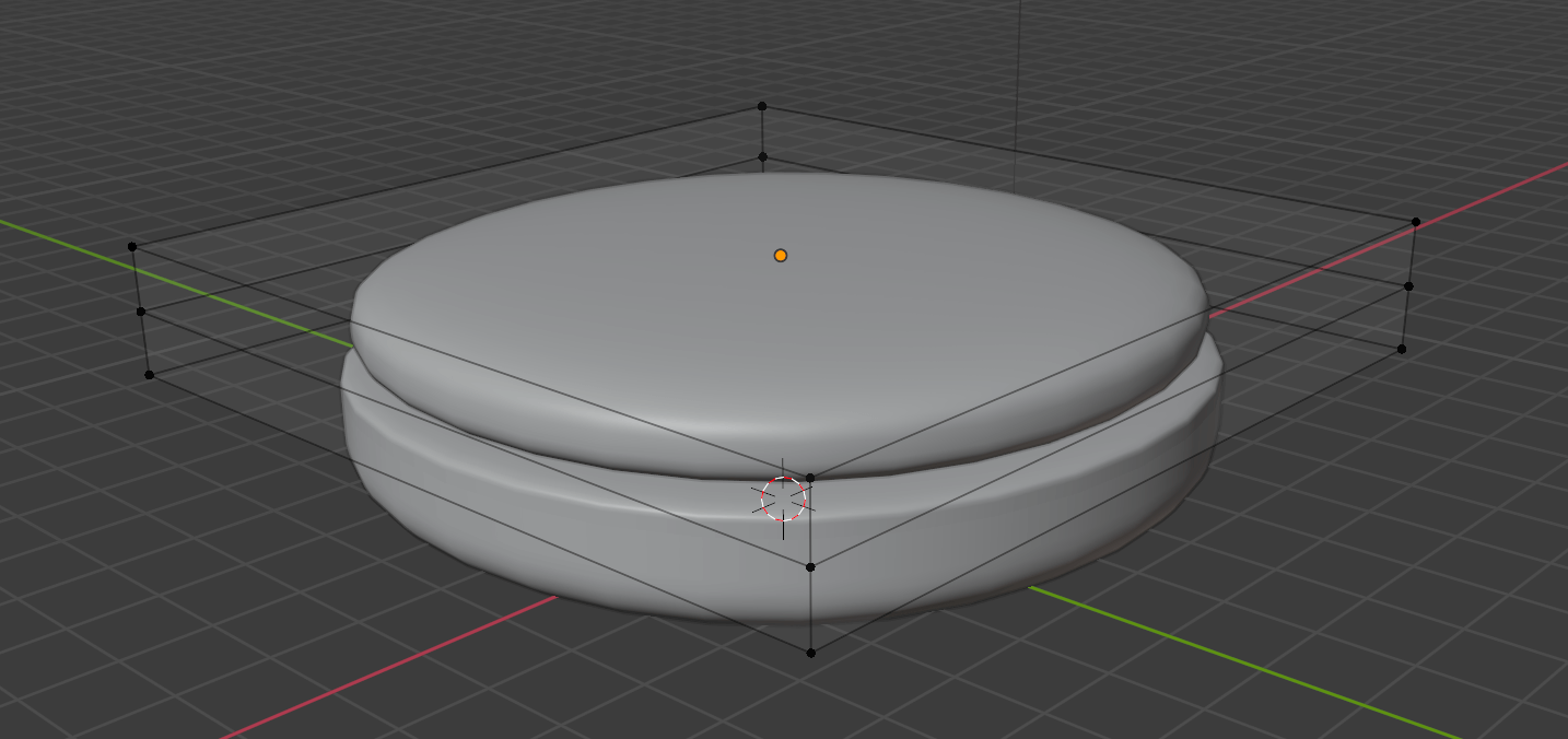
Add the top bun just like we did for the bottom one but make it rounder:
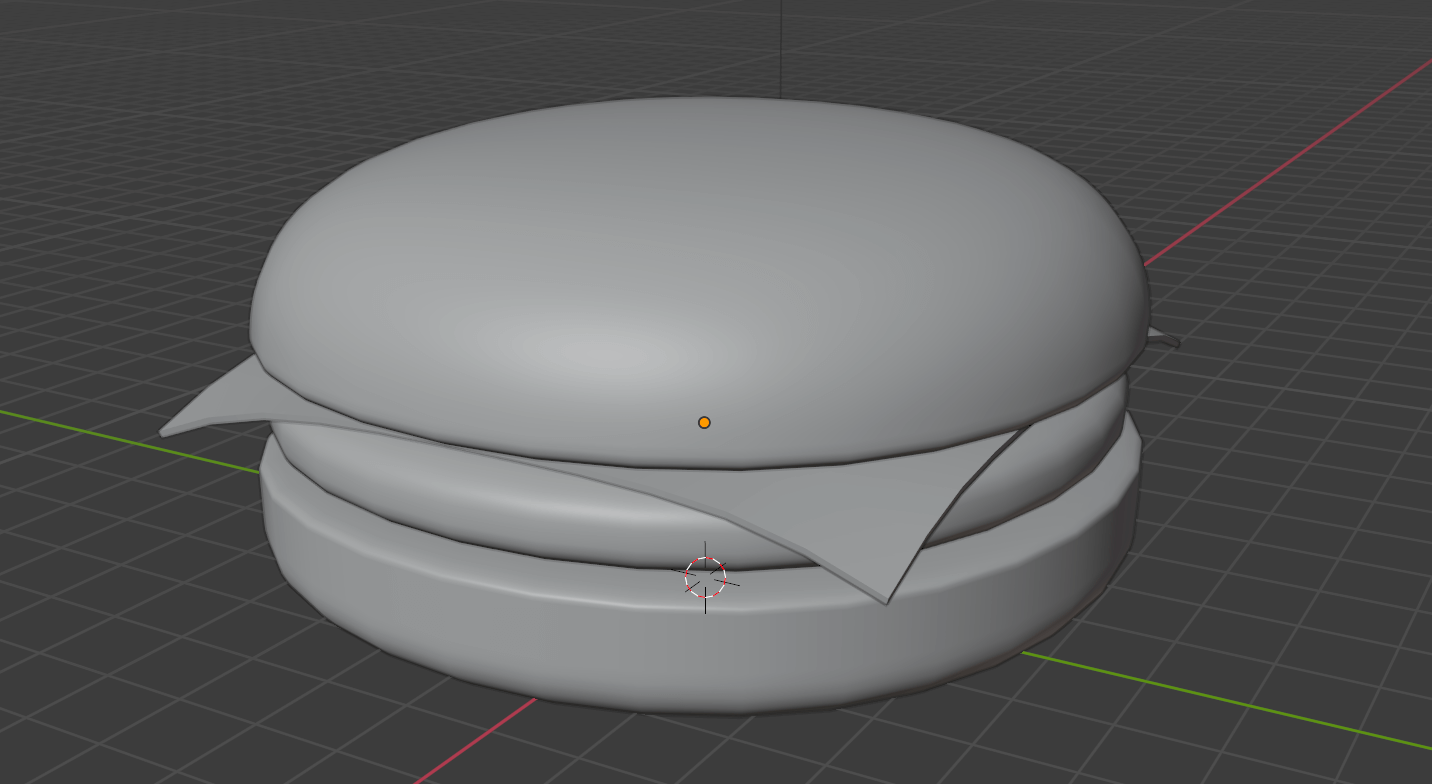
Final tweaks
Now that we have all the ingredients, we can fix the proportions, go back to the previous ingredients, and improve the general shape.
Don’t forget to save.
Materials
It’s time to add some colors and surface properties to our hamburger. For simplicity reasons, we won’t apply textures or use painting.
We need 3 materials —one for the buns, one for the meat and one for the cheese.
Select the bottom bun and go to the Material Properties panel:
You should have no material associated with the bun. If you have one, click on it and press the - button.
To create a new material, click on the New button:
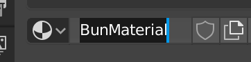
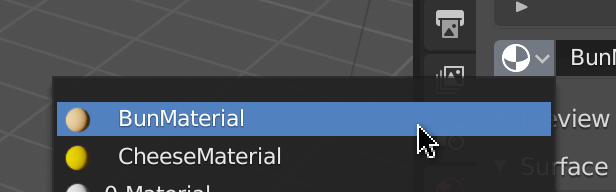
It’s good practice to rename materials. Double click on its name and call it BunMaterial :
Now, tweak the properties to get a tasty color. We only need to change the Base Color and the Roughness :

If you can’t see the color on the 3D Viewport , it might be because you are not using proper shading. To change the shading, press Z and choose Renderer :
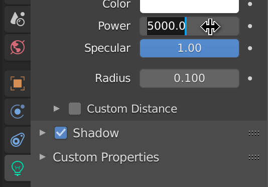
If the hamburger looks really dark, it’s probably because of the light. Select the light, position it a little further away from the hamburger, go to the Object Data Properties panel, and increase its power to 5000 :
Repeat the material process for the meat and the cheese:
For the top bun, you only need to select the BunMaterial you already worked on:
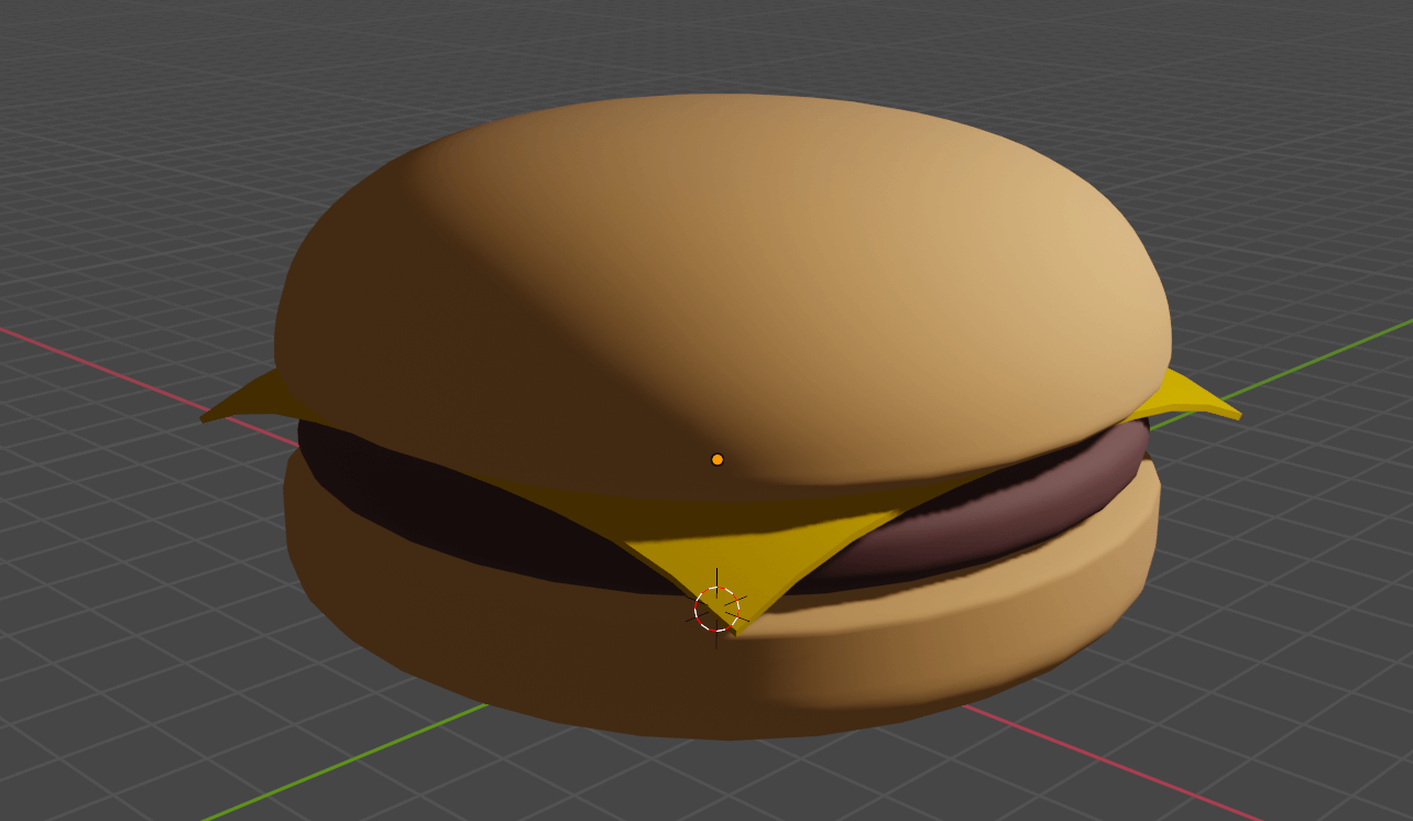
Take your time, delete and try again, until you get a delicious looking hamburger.
You can even add other ingredients like salad, tomatoes, maybe a pickle slice if you’re one of these people— but does anybody even likes pickles?
Don’t forget to save.
Export
It’s finally time to export our hamburger. Download and run the starter. The Three.js scene is ready, and the only thing left is to provide the model.
Select all the ingredients of the hamburger. If you select other elements like lights or cameras, you might export them as well. That can be useful but not in our case.
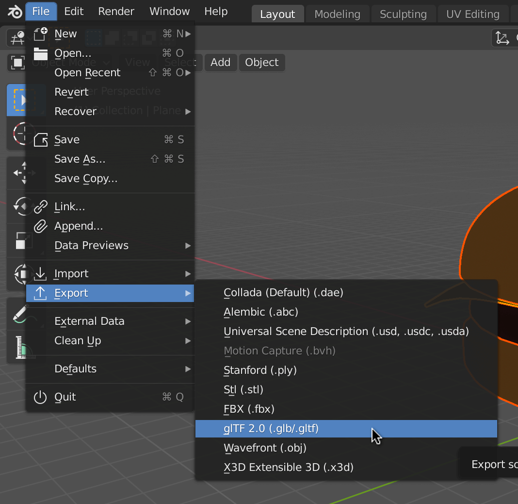
Go to File > Export > glTF 2.0 (.glb/.gltf) :
A panel should open in the middle of the screen. Use it to navigate to the /static/models/ folder of the project (ignore the .gitkeep file if you see it).
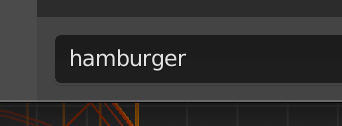
In the bottom part of the panel, choose a name for your file. We will go for hamburger . Do not add the extension:
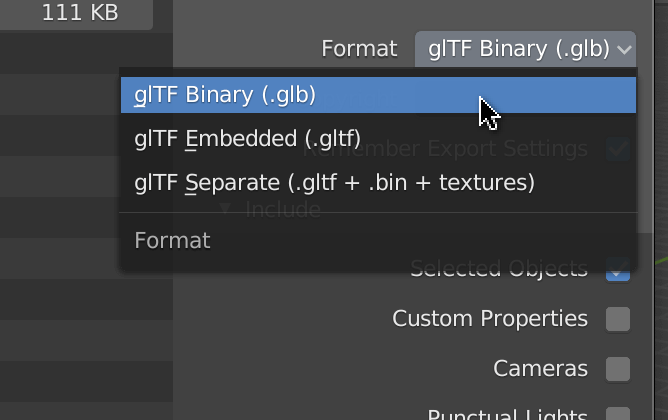
In the right section, we can choose the Format . The choices correspond to the GLTF formats we talked about in the previous lesson. We will go for glTF Binary because we don’t have any texture, and we want the smallest possible file:
For the rest of the properties, here are the settings:
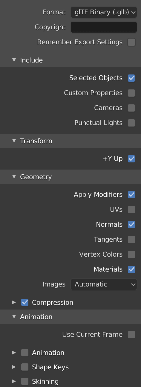
Most of those are obvious but here’s the list
-
Remember Export Settings: To keep these settings the next time we export. - Include:
-
Selected Objects: Only the selected objects. -
Custom Properties: A text information that we can add to any object in Blender, but we didn’t add any. -
Cameras: The cameras. -
Punctual Lights: The lights.
-
- Transform:
-
+Y Up: Convert the axes so that positive Y is the upper one —the default property for Three.js.
-
- Geometry:
-
Apply Modifiers: Applies the modifiers like theSubdivision Surface. If you don’t check this one, you’ll end up with the original cubes instead of your round buns. -
UVs: Adds the UV coordinates. These are the coordinates that Three.js —and other environments— use to apply textures on a geometry. Because we don’t have textures, we don’t need those coordinates. -
Normals: The outside direction of each face. We do need this one if we want the light to work properly. -
Tangents: Works in tandem with the normals, but they are perpendicular to them. -
Vertex Colors: The color associated with each vertex. Useful if we painted the vertices, but we didn’t. -
Materials: The different materials we used. -
Compression: The legendary Draco compression.
-
- Animation
- Everything related to the animations, but we don’t need any of those because we don’t have animations.
Click Export glTF 2.0 and check the file. The file size should be pretty light. Try to export the same hamburger without the compression , and it should be much bigger. In a real project, this would be when you have to decide between using the compressed version and win a few kB load the whole Draco decoder or go for the uncompressed version.
It doesn’t matter as long as we have our file.
Test in Three.js
Run the project and change the hamburger path if needed:
gltfLoader.load(
    '/models/hamburger.glb',

// ...
JavaScript
Copy
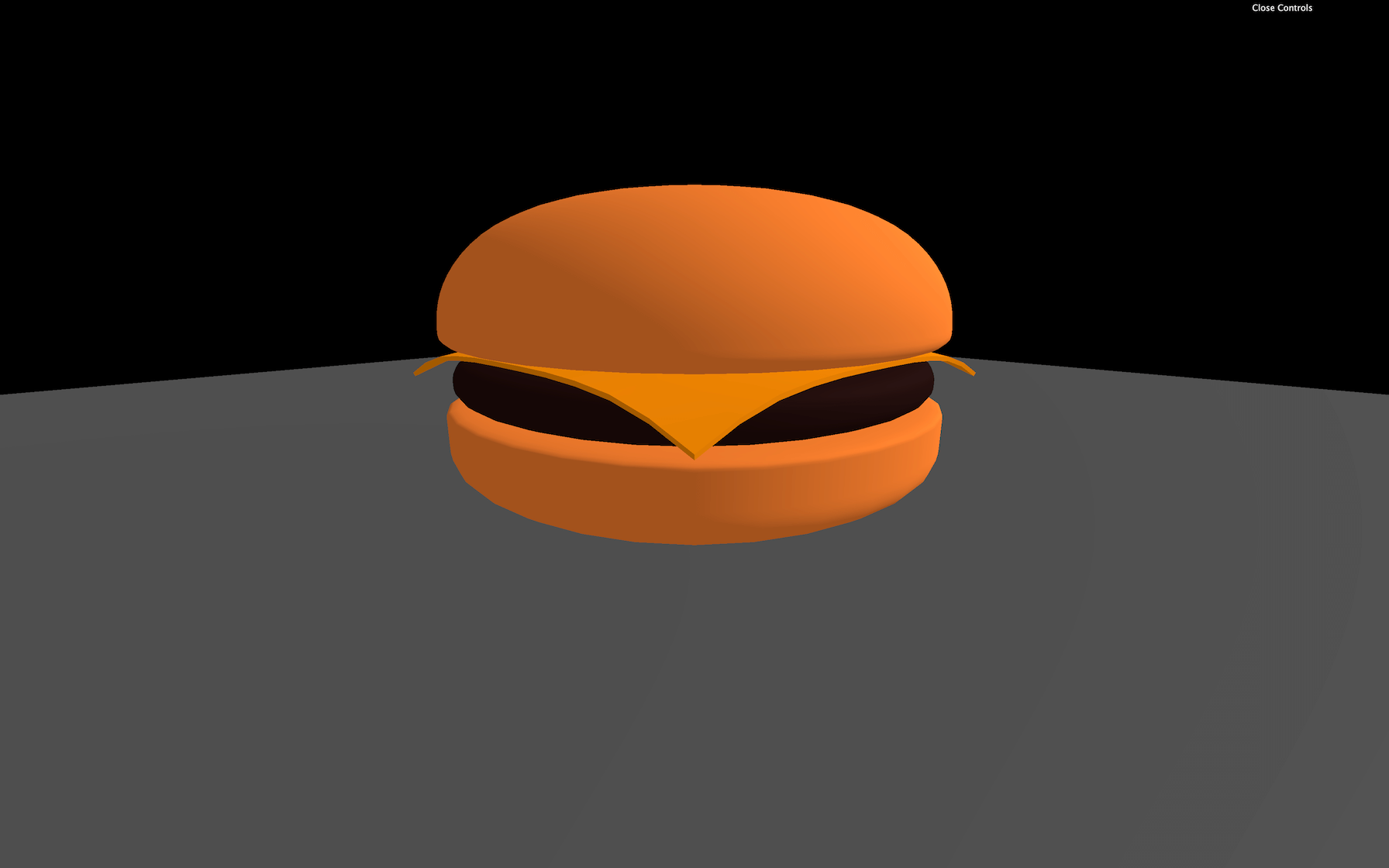
You should see your burger in your Three.js scene.
Regrettably, our hamburger appears way too orange compared to the Blender version. That is due to Three.js settings, and we have to do some tweaks. That will be the next lesson’s topic, but feel free to come back to your burger once you finish applying the features we will learn.
Go further
There are tons of great online tutorials, and most of them are free. Here’s a non-exhaustive list of ressources you can use:
- Blender Youtube Channel: https://www.youtube.com/user/BlenderFoundation
- Blender Guru Youtube Channel: https://www.youtube.com/channel/UCOKHwx1VCdgnxwbjyb9Iu1g
- Grant Abbitt Youtube Channel: https://www.youtube.com/channel/UCZFUrFoqvqlN8seaAeEwjlw
- CGFastTrack: https://www.youtube.com/c/CGFastTrack/videos
- CGCookie: https://cgcookie.com/
Make sure always to follow tutorials using at least version 2.8 of Blender.
23 Realistic render
Difficulty Hard
Introduction
When we imported our hamburger in the previous lesson, the colors were off. To put it in a nutshell: many things participate in a wrong looking model.
Sometimes, we want a very realistic render. Maybe it’s because we want to showcase a real-life product on our website. Or perhaps we are 3D artists, and we want to show off our work with the best possible result. Anyway, we need a render as real as possible.
In this lesson, we will learn many techniques to improve our model looks once rendered in Three.js. Be careful though, some of those techniques can have a performance impact, and some techniques depend on your model. You’ll have to adapt according to the situation.
Setup
We could use our hamburger, but it’s better to try a more realistic model with textures, normal maps, etc. We will use the Flight Helmet from the GLTF Sample Models repository. You can find the model in the /static/models/ folder.
This lesson is also the perfect opportunity to revise what we already learned. That is why there isn’t much code in the starter. We will have to instantiate the loaders, the lights, the shadows, etc., all by ourselves.
We will also use Dat.GUI to tweak as many parameters as possible. That is required if we want to create the perfect environment.
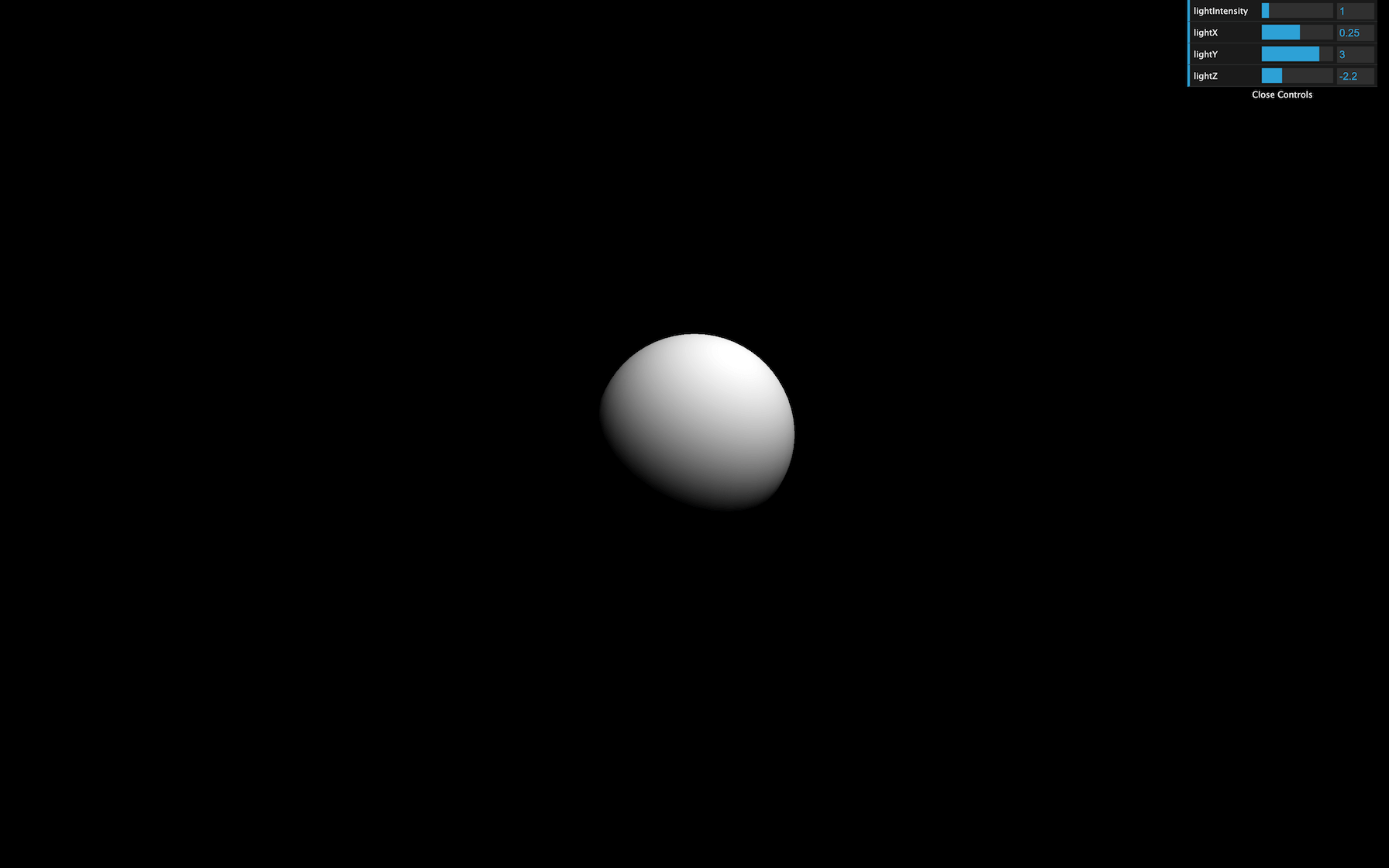
For now, all we have in our scene is a white sphere and an instance of Dat.GUI.
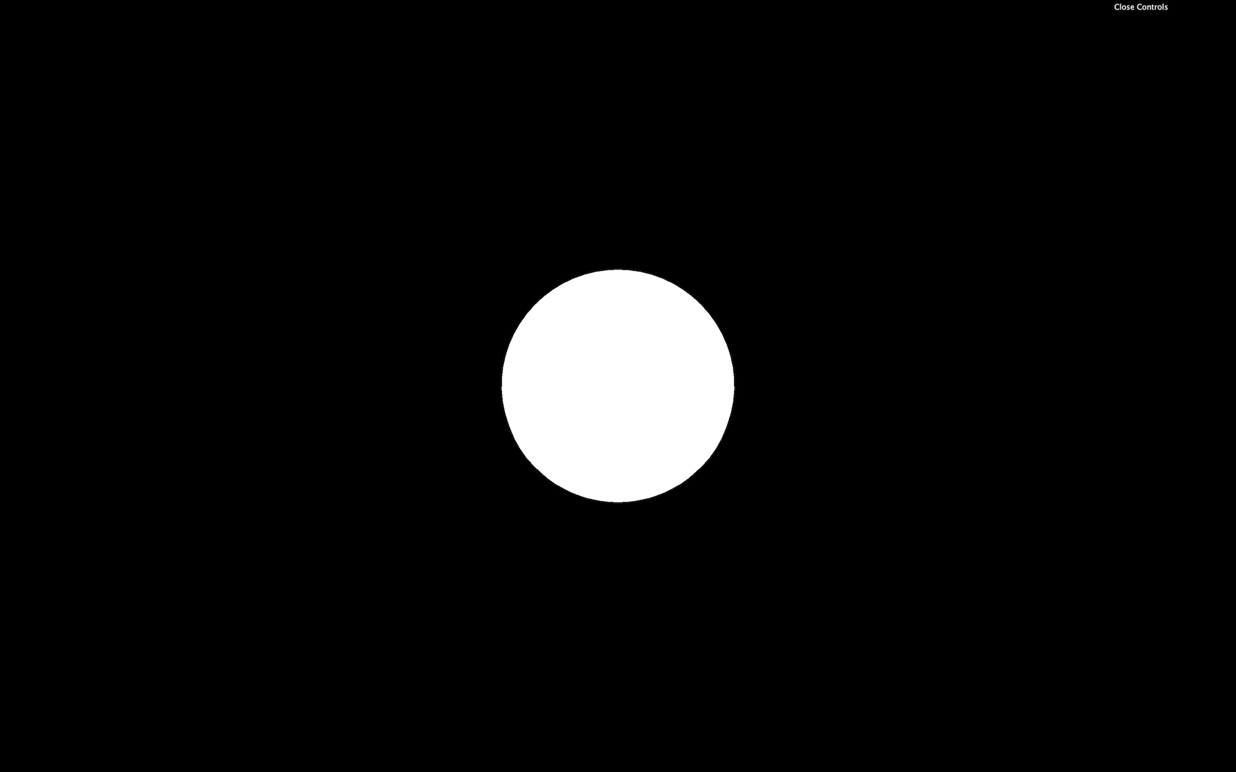
This sphere is just a placeholder to make sure that the starter is working, but we can use it to set up the lights. Change the material of testSphere to MeshStandardMaterial to see the lights we are about to add:
const testSphere = new THREE.Mesh(
    new THREE.SphereBufferGeometry(1, 32, 32),
    new THREE.MeshStandardMaterial()
)
JavaScript
Copy
As you can see, everything has gone black.
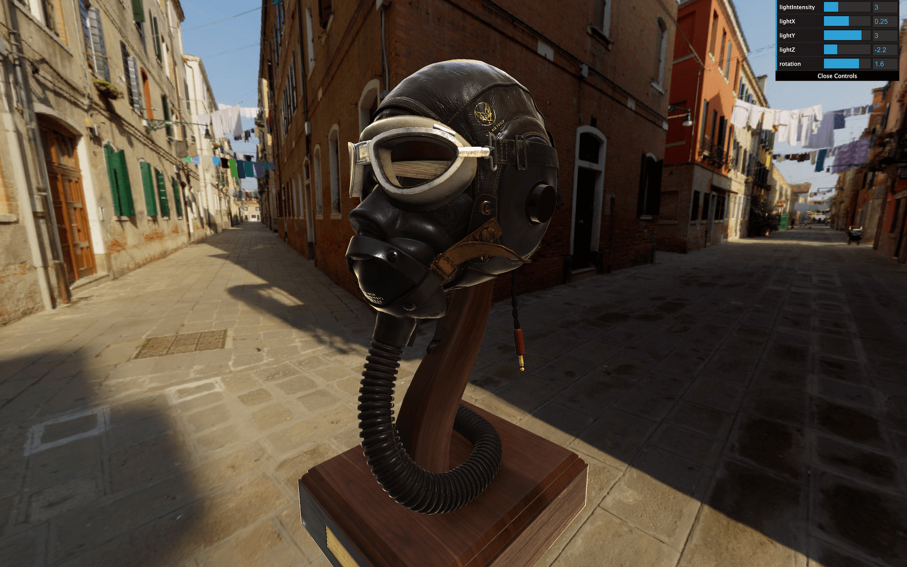
Lights
We are going to use only one DirectionalLight. But how can we have a realistic render with only one light? The environment map will do most of the heavy leverage and simulate light bounce. We could get rid of any light, but the DirectionalLight is important if we want to have more control over the lighting but also to create shadows:
const directionalLight = new THREE.DirectionalLight('#ffffff', 1)
directionalLight.position.set(0.25, 3, - 2.25)
scene.add(directionalLight)
JavaScript
Copy
Let’s add some parameters to our Dat.GUI:
gui.add(directionalLight, 'intensity').min(0).max(10).step(0.001).name('lightIntensity')
gui.add(directionalLight.position, 'x').min(- 5).max(5).step(0.001).name('lightX')
gui.add(directionalLight.position, 'y').min(- 5).max(5).step(0.001).name('lightY')
gui.add(directionalLight.position, 'z').min(- 5).max(5).step(0.001).name('lightZ')
JavaScript
Copy
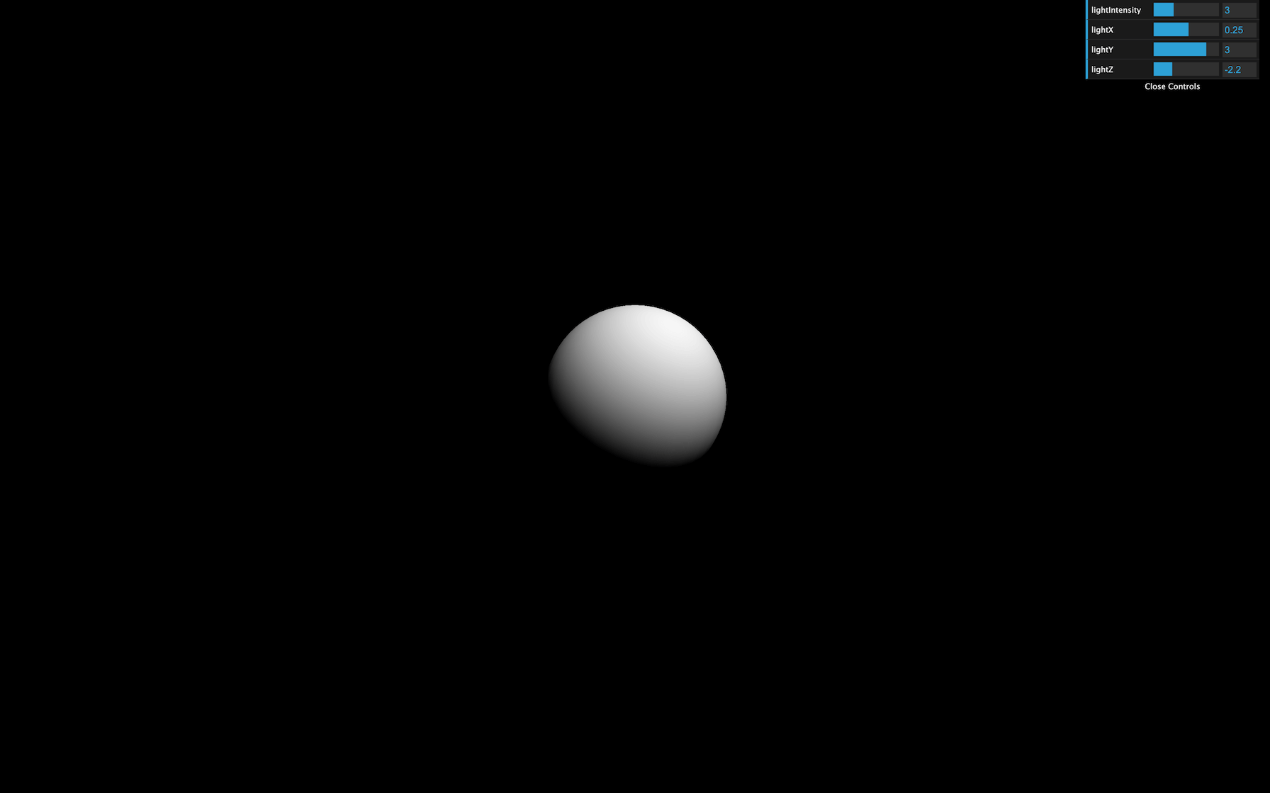
We can now control the position and intensity .
Default Three.js light intensity values aren’t realistic. They are based on an arbitrary scale unit and don’t reflect real-world values. You could say it doesn’t matter, but it’s better to base our scene on realistic and standard values. It might be more comfortable to reproduce real-life conditions that way.
To change Three.js lights for more realistic values, switch the physicallyCorrectLights property of the WebGLRenderer instance (the renderer ) to true :
renderer.physicallyCorrectLights = true
JavaScript
Copy

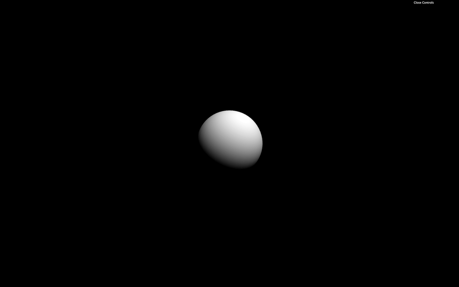
Our light appears dimmed. Let’s increase its intensity to 3 :
const directionalLight = new THREE.DirectionalLight('#ffffff', 3)
JavaScript
Copy
Model
Let’s load our model instead of that test sphere.
First, instantiate the GLTFLoader. We will regroup the different loaders together. There is no particular reason for that but to regroup things together:
import { GLTFLoader } from 'three/examples/jsm/loaders/GLTFLoader.js'

// ...

/**
 * Loaders
 */
const gltfLoader = new GLTFLoader()
JavaScript
Copy
We don’t need the DRACOLoader because the model isn’t compressed. But if you load a Draco compressed model, instantiate the DRACOLoaderas we did in a previous lesson.
We can now load our model located in /static/models/FlightHelmet/glTF/FlightHelmet.gltf :
/**
 * Models
 */
gltfLoader.load(
    '/models/FlightHelmet/glTF/FlightHelmet.gltf',
    (gltf) =>
    {
        console.log('success')
        console.log(gltf)
    }
)
JavaScript
Copy
As always, go slow, make sure that the model is well loaded with no error, and study the imported result.
Because it’s a complex model, we will simply add the gltf.scene group to our own scene:
gltfLoader.load(
    '/models/FlightHelmet/glTF/FlightHelmet.gltf',
    (gltf) =>
    {
        scene.add(gltf.scene)
    }
)
JavaScript
Copy
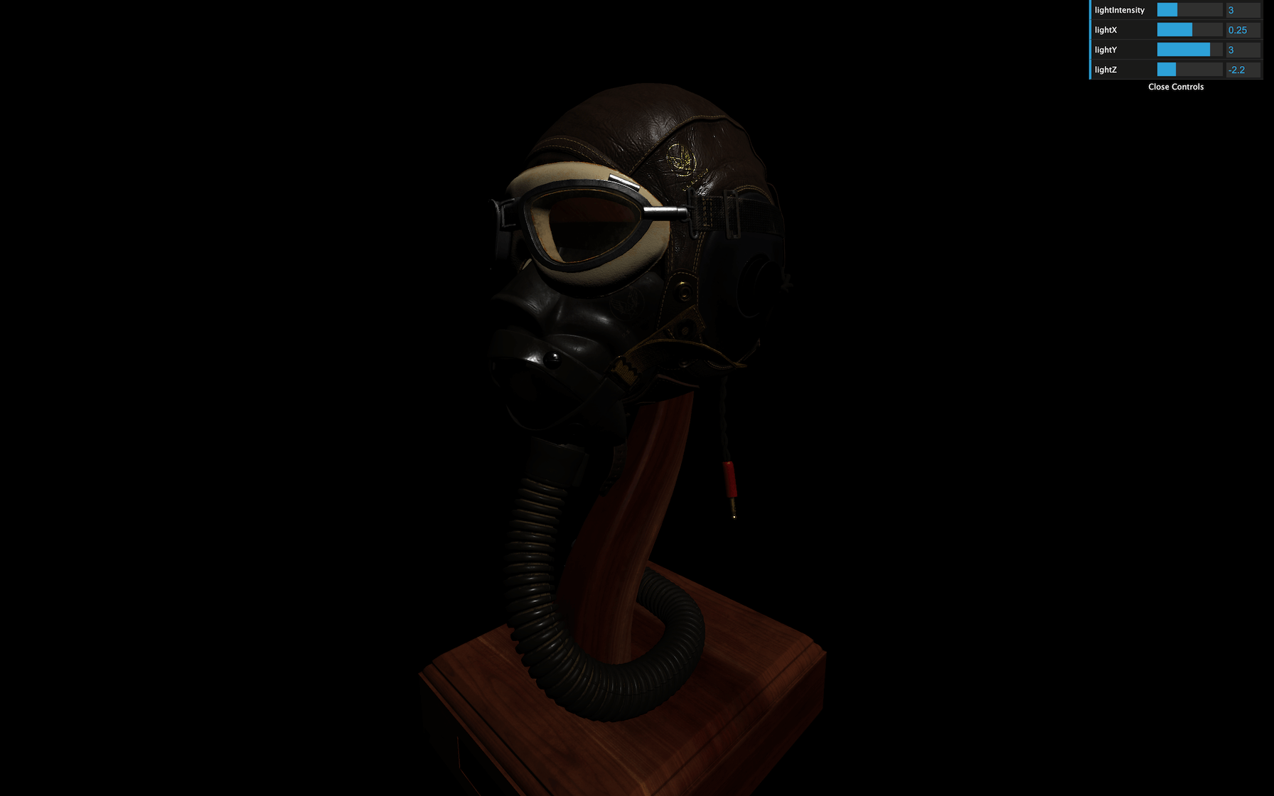
If you can’t see it but don’t get any error, Remove your testSphere and zoom a little. The explanation is simple: the loaded model is too small.
Increase its scale, move it down a little, and rotate it so it fits our camera view better:
gltfLoader.load(
    '/models/FlightHelmet/glTF/FlightHelmet.gltf',
    (gltf) =>
    {
        gltf.scene.scale.set(10, 10, 10)
        gltf.scene.position.set(0, - 4, 0)
        gltf.scene.rotation.y = Math.PI * 0.5
        scene.add(gltf.scene)
    }
)
JavaScript
Copy
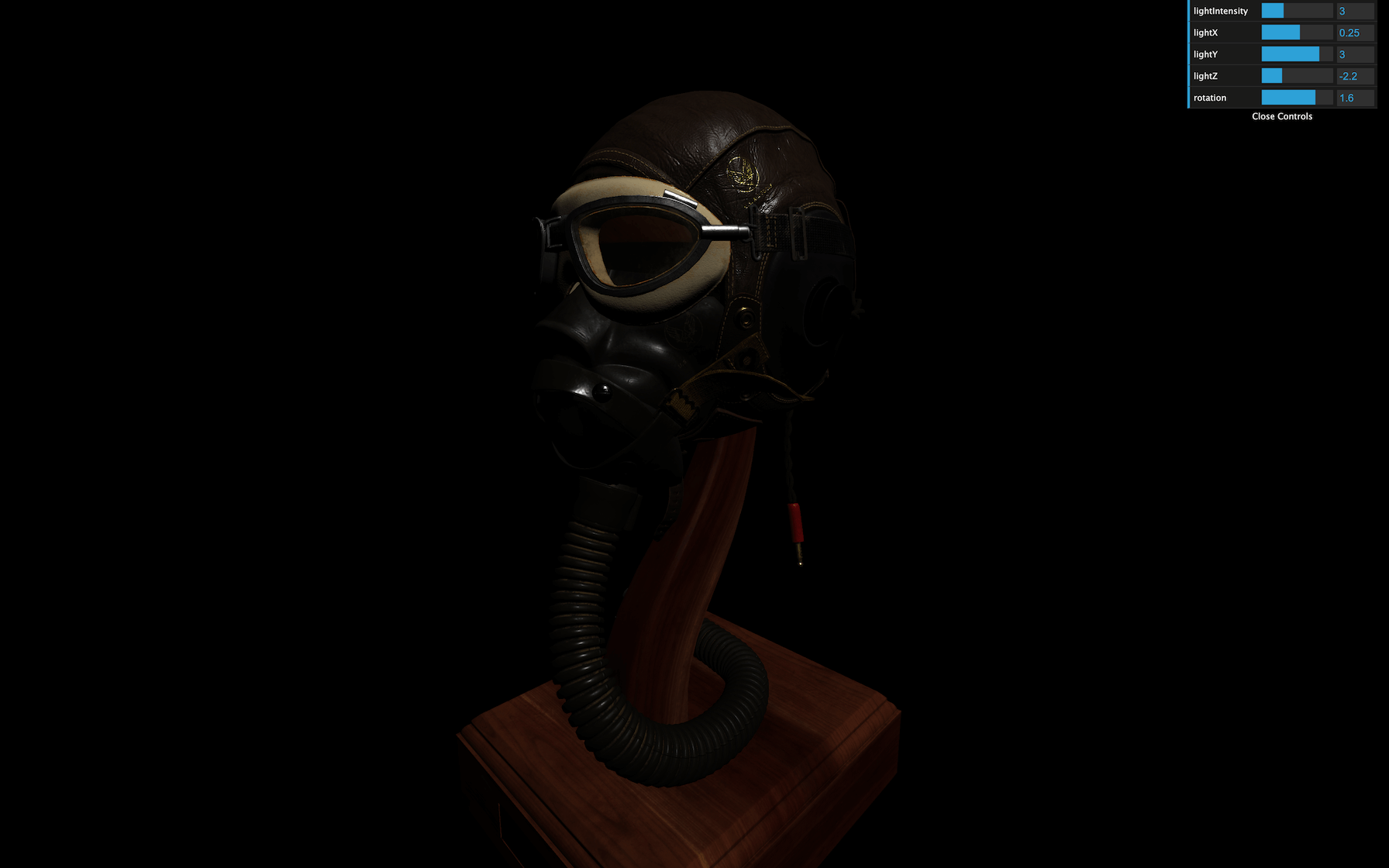
Let’s also add a tweak to rotate the whole model in our Dat.GUI:
gltfLoader.load(
    '/models/FlightHelmet/glTF/FlightHelmet.gltf',
    (gltf) =>
    {
        // ...

        gui.add(gltf.scene.rotation, 'y').min(- Math.PI).max(Math.PI).step(0.001).name('rotation')
    }
)
JavaScript
Copy
Environment map
We can’t see much of our model because we have only one weak DirectionalLight. As we said previously, the lighting will be taken care of by the environment map.
We already talked about the environment map in the Materials lesson. An environment map is like a photo of the surrounding. It can be a 360 photo or 6 photos that, once put together, compose a cube.
We will use the environment map both for the background and to illuminate our model.
Load the environment map
First, let’s load our environment map. There are multiple textures located in the /static/textures/environmentMaps/ folder. We are going to use the first one.
Because these textures are composed of 6 images (a cube), we have to use a CubeTextureLoader.
Add the CubeTextureLoader to our loaders:
const cubeTextureLoader = new THREE.CubeTextureLoader()
JavaScript
Copy
Now we can load the textures. The order is positive x , negative x , positive y , negative y , positive z , and negative z .
Add it after creating the scene :
/**
 * Environment map
 */
const environmentMap = cubeTextureLoader.load([
    '/textures/environmentMaps/0/px.jpg',
    '/textures/environmentMaps/0/nx.jpg',
    '/textures/environmentMaps/0/py.jpg',
    '/textures/environmentMaps/0/ny.jpg',
    '/textures/environmentMaps/0/pz.jpg',
    '/textures/environmentMaps/0/nz.jpg'
])
JavaScript
Copy
Nothing should have change because we are loading the environment map but we don’t use it yet.
Check the logs for potential errors.
Apply the environment map to the background
To add the environment map in our scene’s background, we could create a massive cube around the scene, set its face to be visible on the inside, and apply its texture. It should work and looks ok, but instead, let’s use a feature included in Three.js.
To apply an environmentMap on a scene, use the cube texture on the Scene’s background property. Make sure to do this after creating the environmentMap and the scene :
scene.background = environmentMap
JavaScript
Copy

And that’s all. You should see the environment map in the background.
Apply the environment map to the model
One essential feature to get a realistic render is to use our environment map to lighten our model.
We have already covered how to apply an environment map to a MeshStandardMaterial with the envMap property. The problem is that our model is composed of many Meshes. What we can do is use the traverse(...) method available on every Object3D —and classes that inherit from it like Group and Mesh.
Instead of doing it in the success callback function, we will create a updateAllMaterials function that will get handy later. Create this function before the environment map:
/**
 * Update all materials
 */
const updateAllMaterials = () =>
{
    scene.traverse((child) =>
    {
        console.log(child)
    })
}
JavaScript
Copy
Now call it when the model is loaded and added to the scene:
gltfLoader.load(
    '/models/FlightHelmet/glTF/FlightHelmet.gltf',
    (gltf) =>
    {
        // ...

        updateAllMaterials()
    }
)
JavaScript
Copy
You should see all the children and grand children in the logs.
Instead of logging the children, we want to apply the environment map to each material that should have it.
It would make no sense to apply the environment map to the lights, the camera, the group, etc. We only want to apply the environment map to the Meshes that have a MeshStandardMaterial.
What we can do is test if the child is an instance of THREE.Mesh and if its material is an instance of THREE.MeshStandardMaterial :
const updateAllMaterials = () =>
{
    scene.traverse((child) =>
    {
        if(child instanceof THREE.Mesh && child.material instanceof THREE.MeshStandardMaterial)
        {
            console.log(child)
        }
    })
}
JavaScript
Copy
We now only log the children that support environment maps. Let’s change their envMap property in the material property:
const updateAllMaterials = () =>
{
    scene.traverse((child) =>
    {
        if(child instanceof THREE.Mesh && child.material instanceof THREE.MeshStandardMaterial)
        {
            child.material.envMap = environmentMap
        }
    })
}
JavaScript
Copy

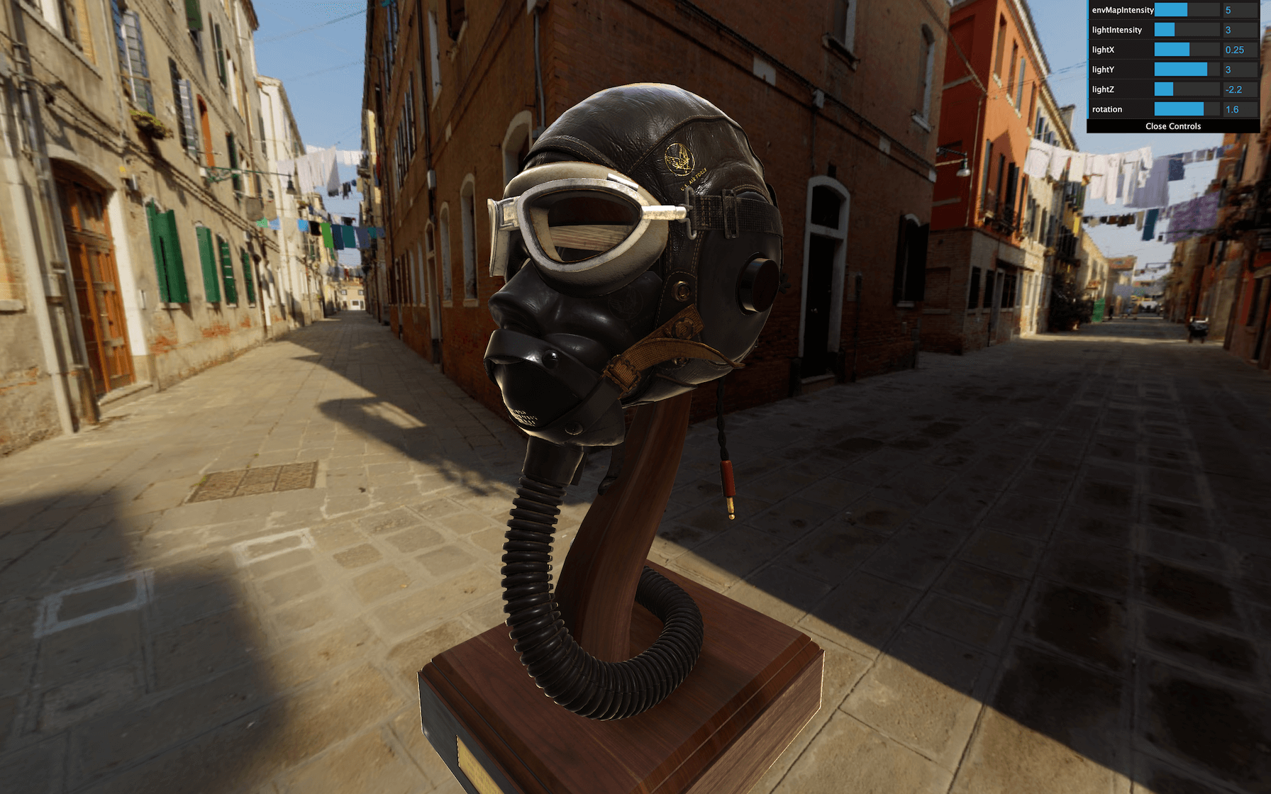
Can’t see much of a difference? Increase the envMapIntensity to 5 :
const updateAllMaterials = () =>
{
    scene.traverse((child) =>
    {
        if(child instanceof THREE.Mesh && child.material instanceof THREE.MeshStandardMaterial)
        {
            child.material.envMap = environmentMap
            child.material.envMapIntensity = 5
        }
    })
}
JavaScript
Copy
That’s better. We get a nice and realistic lighting.
For more control, let’s add the envMapIntensity property to our Dat.GUI. The problem is that we need only one property to tweak, and, when changed, this value should be applied to all children materials.
We can, however, use the debugObject technique as we did in a previous lesson. Right after instantiating Dat.GUI, create a debugObject :
const gui = new dat.GUI()
const debugObject = {}
JavaScript
Copy
Then, in the environment map code section, add an envMapIntensity property to that object as well as to your Dat.GUI:
debugObject.envMapIntensity = 5
gui.add(debugObject, 'envMapIntensity').min(0).max(10).step(0.001)
JavaScript
Copy
We now have the envMapIntensity tweak, but changing the value isn’t updating the scene and its children. We should now call the updateAllMaterials function when the tweak value changes and use the debugObject.envMapIntensity value in the updateAllMaterials function:
const updateAllMaterials = () =>
{
    // ...
            child.material.envMapIntensity = debugObject.envMapIntensity
    // ...
}

// ...

debugObject.envMapIntensity = 5
gui.add(debugObject, 'envMapIntensity').min(0).max(10).step(0.001).onChange(updateAllMaterials)
JavaScript
Copy
We can now change all Meshes environment map intensity with only one tweak directly in our debug interface.
Apply the environment map as default
There is an easier way of applying the environment map to all objects. We can update the environment property of the scene just like we changed the background property:
scene.environment = environmentMap
GLSL
Copy
Unluckily, we cannot change the environment map intensity of each material directly from the scene, so we still need our updateAllMaterials function, but it’s a perfectly viable solution.
Renderer
Things are getting more and more realistic, but we still feel that it’s all fake. We need to work on the colors, and this is a matter of WebGLRenderer properties.
Output encoding
Without going too much into details, the outputEncoding property controls the output render encoding. By default, the value of outputEncoding is THREE.LinearEncoding , which looks ok, but not realistic.
The recommended value for the outputEncoding is THREE.sRGBEncoding :
renderer.outputEncoding = THREE.sRGBEncoding
JavaScript
Copy
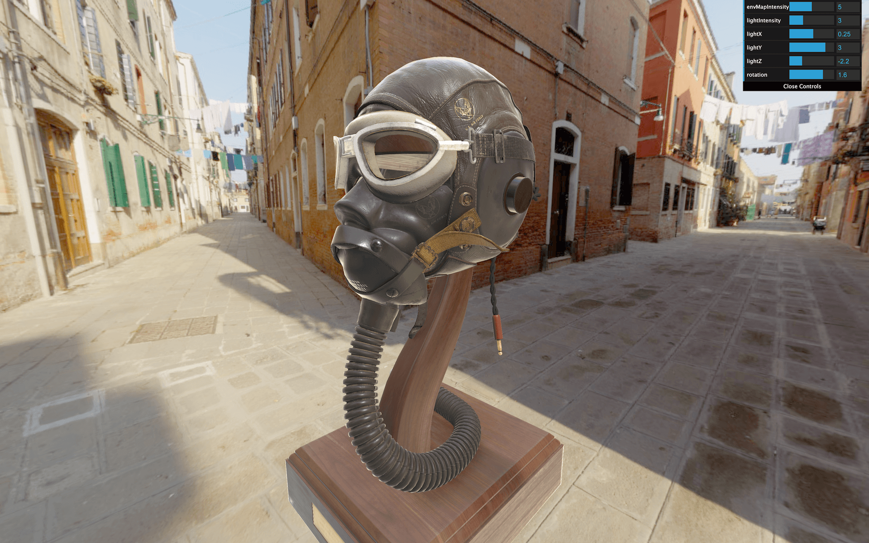
You should see much brighter textures that will also impact the environment map.
Another possible value is THREE.GammaEncoding . This encoding has the advantage of letting you play on a value called gammaFactor that would act a little like the brightness, but we won’t use this one in the lesson.
The Gamma Encoding is a way of storing colors while optimizing how bright and dark values are stored according to human eye sensitivity. When we use the sRGBEncoding , it’s like using the GammaEncoding with a default gamma factor of 2.2 , which is the common value.
You can find out more about this topic here
- https://www.donmccurdy.com/2020/06/17/color-management-in-threejs/
- https://medium.com/game-dev-daily/the-srgb-learning-curve-773b7f68cf7a
While some might think that GammaEncoding is better than sRGBEncoding because we can control the gamma factor for a darker or brighter scene, this physically doesn’t seem right, and we will see how to manage the “brightness” in a better way later.
Textures encoding
You might not have noticed it, but the environment map colors are wrong. They appear grayish and toned down. Even if the effect looks pretty good, it’s more satisfying to preserve the right colors.
The problem is that our renderer outputEncoding is THREE.sRGBEncoding , yet the environment map texture is by default THREE.LinearEncoding .
The rule is straightforward. All textures that we can see directly —like the map —should have THREE.sRGBEncoding as encoding, and all other textures — such as normalMap —should have THREE.LinearEncoding .
We can see the environmentMap texture directly, so we have to change its encoding to THREE.sRGBEncoding :
environmentMap.encoding = THREE.sRGBEncoding
GLSL
Copy
But what about the model textures?
Fortunately, the GLTFLoader implemented this rule, and all the textures loaded from it will have the right encoding automatically.
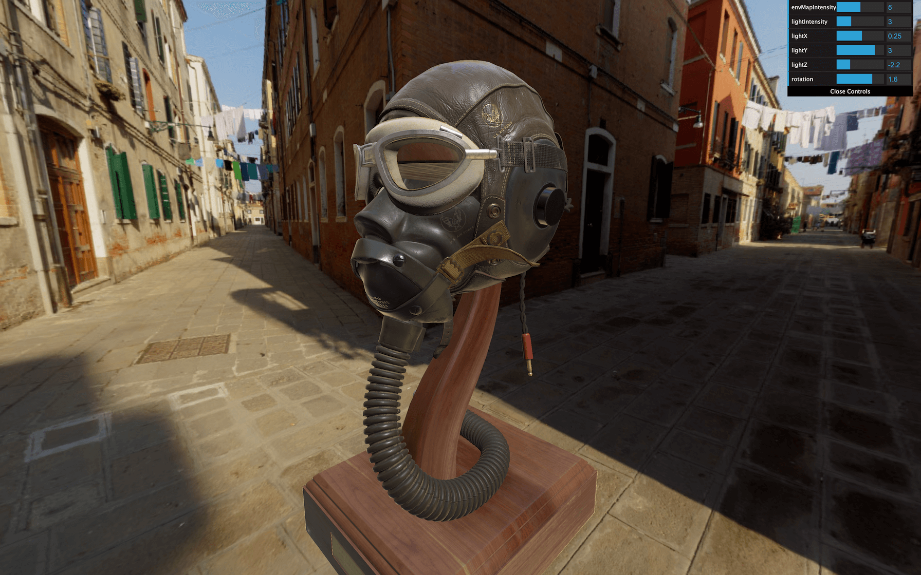
Tone mapping
The tone mapping intends to convert High Dynamic Range (HDR) values to Low Dynamic Range (LDR) values. HDR is much more than the following interpretation, but you can see that like images where the color values can go beyond 1 . It’s useful if we want to store light information because light doesn’t have intensity limits.
While our assets are not HDR, the tone mapping effect can have a realistic result as if the camera was poorly adjusted.
To change the tone mapping, update the toneMapping property on the WebGLRenderer.
There are multiple possible values:
-
THREE.NoToneMapping(default) THREE.LinearToneMappingTHREE.ReinhardToneMappingTHREE.CineonToneMappingTHREE.ACESFilmicToneMapping
Test these tone mapping:
renderer.toneMapping = THREE.ACESFilmicToneMapping
JavaScript
Copy

To appreciate the difference, let’s add the toneMapping to our Dat.GUI. We can create a dropdown tweak by sending an object with different keys and values as the third parameter of gui.add(...) :
gui.add(renderer, 'toneMapping', {
    No: THREE.NoToneMapping,
    Linear: THREE.LinearToneMapping,
    Reinhard: THREE.ReinhardToneMapping,
    Cineon: THREE.CineonToneMapping,
    ACESFilmic: THREE.ACESFilmicToneMapping
})
JavaScript
Copy
Unfortunately, changing this tweak will result in a warning in the console, looking like THREE.WebGLProgram: Unsupported toneMapping: 3 . The problem is a bug with Dat.GUI interpreting the values of the object as a String.
For example, if we use THREE.ReinhardToneMapping , the value behind this constant is 3 as a Number . But once we change the tweak for tone mapping, Dat.GUI will send '3' as a String which will result in the error previously mentioned.
We can fix that by converting the value to a Number in the change event callback:
gui
    .add(renderer, 'toneMapping', {
        No: THREE.NoToneMapping,
        Linear: THREE.LinearToneMapping,
        Reinhard: THREE.ReinhardToneMapping,
        Cineon: THREE.CineonToneMapping,
        ACESFilmic: THREE.ACESFilmicToneMapping
    })
    .onFinishChange(() =>
    {
        renderer.toneMapping = Number(renderer.toneMapping)
    })
JavaScript
Copy
Changing the tone mapping should work. Nevertheless, if you watch closely, you’ll see that the tone mapping changed for the environment map in the background, but not for the model itself.
We need to find a way to tell the materials that they need to be updated and we already did that in the updateAllMaterials function. What we can do is call this function right after changing the toneMapping :
    .onFinishChange(() =>
    {
        renderer.toneMapping = Number(renderer.toneMapping)
        updateAllMaterials()
    })
JavaScript
Copy
The materials should also update when changing the tone mapping.
We can also change the tone mapping exposure. You can see that like how much light we let in and the algorithm will handle it its way. To change this value, we must update the toneMappingExposure property directly on the renderer :
renderer.toneMappingExposure = 3
JavaScript
Copy
Let’s add it to Dat.GUI as well:
gui.add(renderer, 'toneMappingExposure').min(0).max(10).step(0.001)
JavaScript
Copy
Feel free to choose your favorite toneMapping for the rest of the lesson, but here we will go for THREE.ReinhardToneMapping .
Antialiasing
We call aliasing an artifact that might appear in some situations where we can see a stair-like effect, usually on the edge of geometries.
Our model isn’t subject to that problem because there is a lot of details, but if you have a screen with a pixel ratio of 1 . Look at the edges —especially the bright ones— rotate the camera slowly, and you might see the problem:

It’s a well-known problem. When the rendering of a pixel occurs, it tests what geometry is being rendered in that pixel. It calculates the color, and, in the end, that color appears on the screen.
But geometry edges are usually not perfectly aligned with vertical lines and horizontal lines of pixel of your screen and this is why you get this stair-like artifact named aliasing .
There are many ways of fixing that problem, and developers have been struggling with it for many years.
One easy solution would be to increase our render’s resolution, let’s say to the double. When resized to it’s normal-sized, each pixel color will automatically be averaged from the 4 pixels rendered.
This solution is called super sampling (SSAA) or fullscreen sampling (FSAA), and it’s the easiest and more efficient one. Unfortunately, that means 4 times more pixels to render, which can result in performance issues.
The other solution is called multi sampling (MSAA). Again, the idea is to render multiple values per pixel (usually 4) like for the super sampling but only on the geometries’ edges. The values of the pixel are then averaged to get the final pixel value.
The most recent GPU can perform this multi sampling anti-aliasing, and Three.js handles the setup automatically. We just need to change the antialias property to true during the instantiating — and not after:
const renderer = new THREE.WebGLRenderer({
    canvas: canvas,
    antialias: true
})
JavaScript
Copy
Those aliasing artifacts should be gone now.
Using the antialias exhausts some resources. As we said earlier, screens with a pixel ratio above 1 don’t really need antialias. One right way to do this would be to activate it only for screens with a pixel ratio below 2 . We will see how to achieve that in a future lesson, along with other optimizations.
Shadows
The final touch for a realistic render is to add shadows. First, toggle the shadows on WebGLRenderer. Then, change the shadow type to THREE.PCFSoftShadowMap as we did in the Shadows lesson:
renderer.shadowMap.enabled = true
renderer.shadowMap.type = THREE.PCFSoftShadowMap
JavaScript
Copy
Activate it on the DirectionalLight:
directionalLight.castShadow = true
JavaScript
Copy
We also need to set the camera that handles the shadow for this light.
Add a CameraHelper to the directionalLight.shadow.camera :
const directionalLightCameraHelper = new THREE.CameraHelper(directionalLight.shadow.camera)
scene.add(directionalLightCameraHelper)
JavaScript
Copy
We can now see accurately what the shadow camera will render. The box should already fit pretty nicely with the scene. Let’s reduce the far value:
directionalLight.shadow.camera.far = 15
JavaScript
Copy
We can remove or comment the directionalLightCameraHelper .
As we want realistic and precise shadows and because we have only one light, we can increase the shadow map size to 1024x1024 without fearing a frame rate drop.
directionalLight.shadow.mapSize.set(1024, 1024)
JavaScript
Copy
Finally, we can activate the shadows on all the Meshes of our model. As we are already traversing the scene in the updateAllMaterials function, let’s simply activate both castShadow and receiveShadow on all the children:
const updateAllMaterials = () =>
{
    scene.traverse((child) =>
    {
        if(child instanceof THREE.Mesh && child.material instanceof THREE.MeshStandardMaterial)
        {
            // ...

            child.castShadow = true
            child.receiveShadow = true
        }
    })
}
JavaScript
Copy
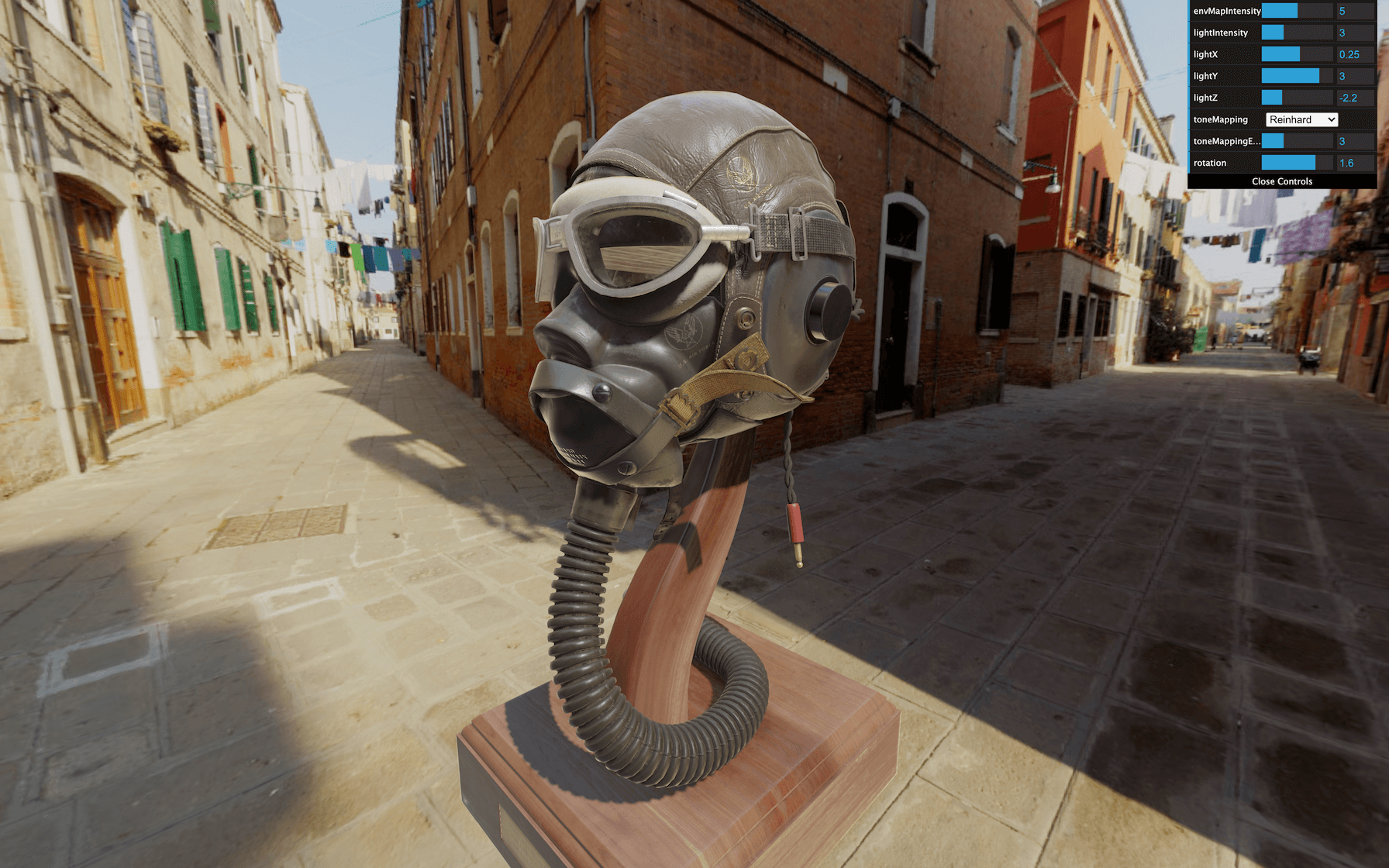
You should now observe an accurate shadow, mostly on the wood base and inside the model.
Final tweaks
Now that we have everything in place, we can tweak the values, make sure the directionalLight corresponds to the light in the environment map, try other environment maps, test different tone mappings, add animation, etc.
It’s up to you. Take your time, stop looking at your render, and look around because you need real-life markers, make sure your screen colors are good, maybe show your work to your friends to get an external point of view until everything is correctly set.
Hamburger
Let’s try with our hamburger. A version is already located in /static/models/hamburger.glb .
This file isn’t Draco compressed. If you are using your model, make sure it’s not compressed or add the DRACOLoader to the GLTFLoader as we did in the Imported Model lesson.
Replace the path to load the hamburger and change the scale and position:
gltfLoader.load(
    '/models/hamburger.glb',
    (gltf) =>
    {
        gltf.scene.scale.set(0.3, 0.3, 0.3)
        gltf.scene.position.set(0, - 1, 0)
        scene.add(gltf.scene)

        updateAllMaterials()
    }
)
JavaScript
Copy
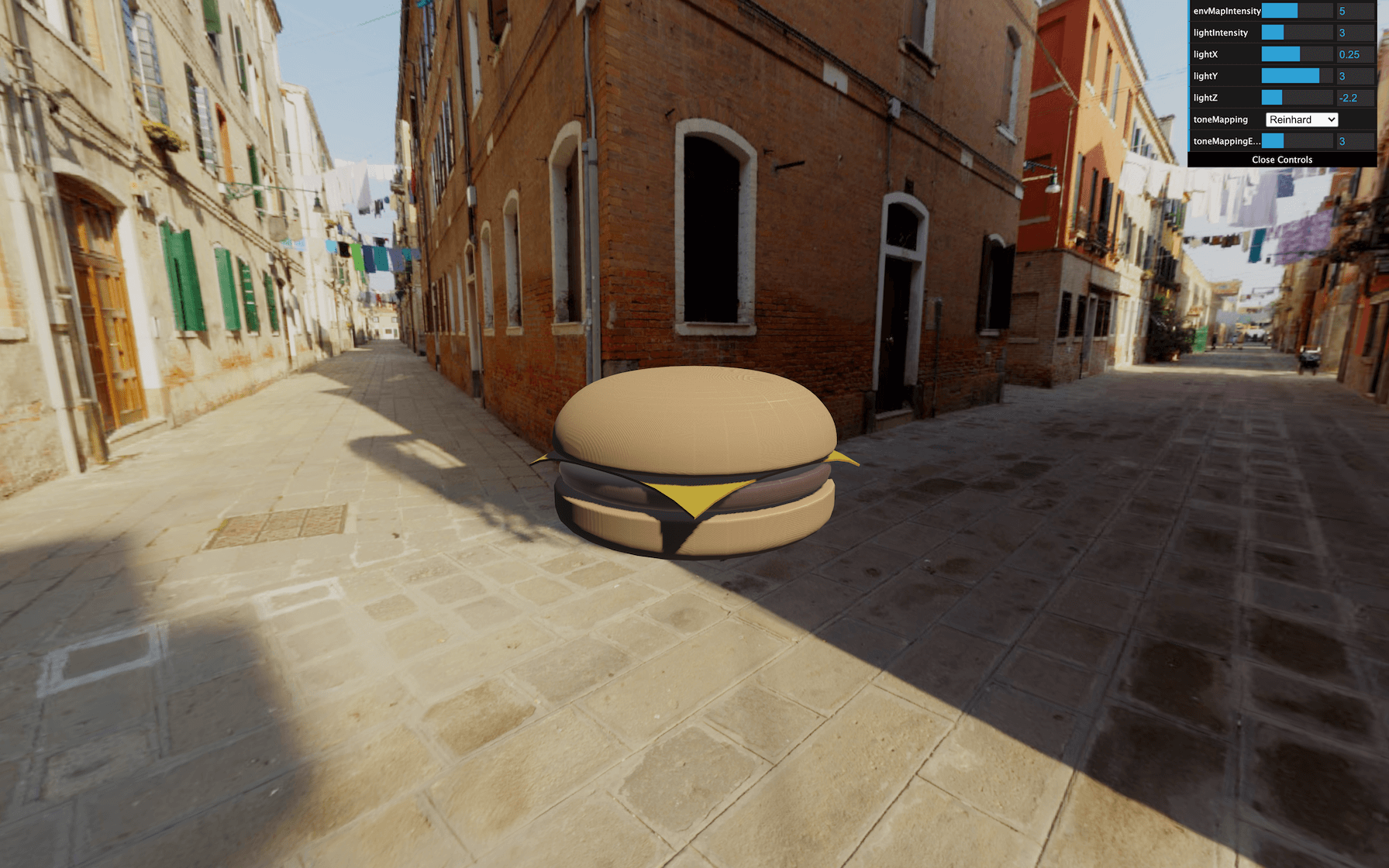
Your hamburger appears, but some nasty strips cover its surface.
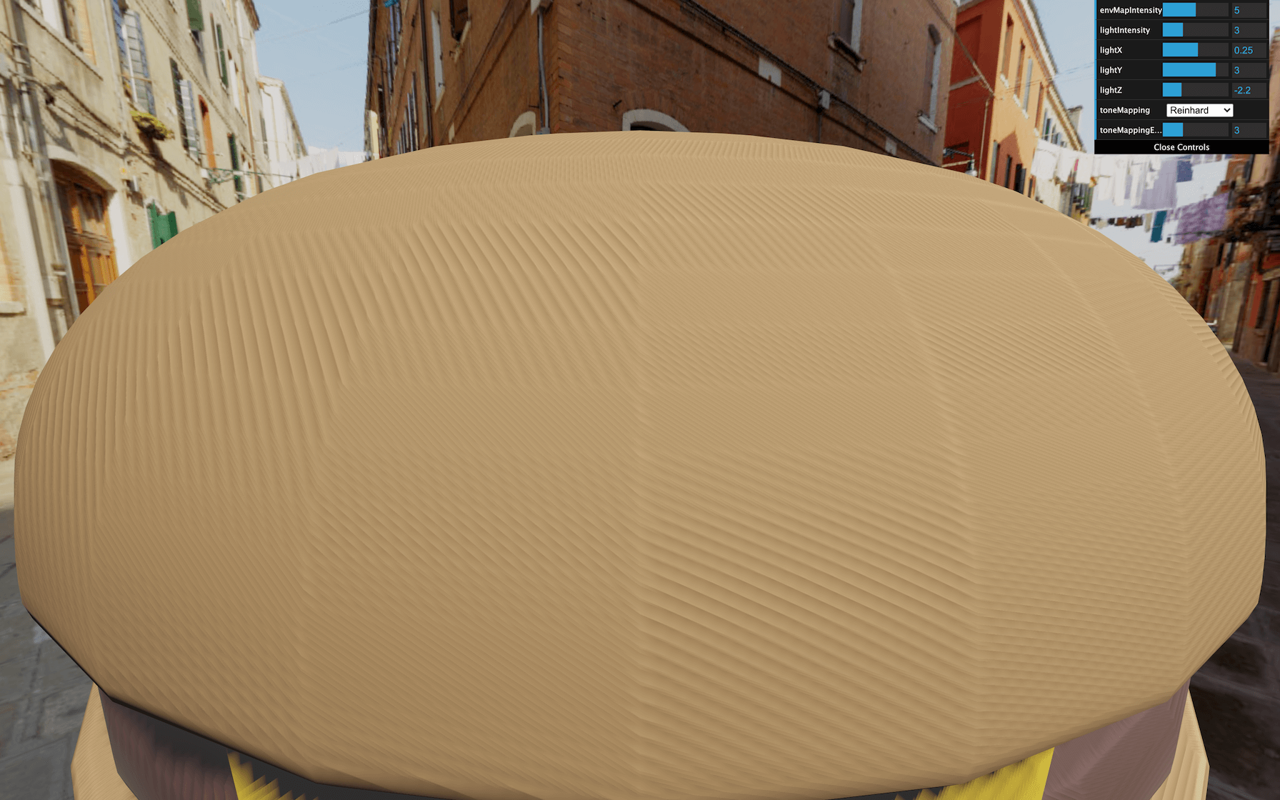
No we didn’t let the hamburger burn on the grill.
These artifacts are called shadow acne. Shadow acne can occur on both smooth and flat surfaces for precision reasons when calculating if the surface is in the shadow or not. What’s happening here is that the hamburger is casting a shadow on its own surface.
We have to tweak the light shadow 's bias and normalBias properties to fix this shadow acne.
The bias usually helps for flat surfaces. It’s not our case here, but if you have the problem on flat surfaces, try to increase the bias slightly until the acne disappears.
The normalBias usually helps for rounded surfaces, which is our case. Let’s increase it until the shadow acne is barely visible:
directionalLight.shadow.normalBias = 0.05
JavaScript
Copy
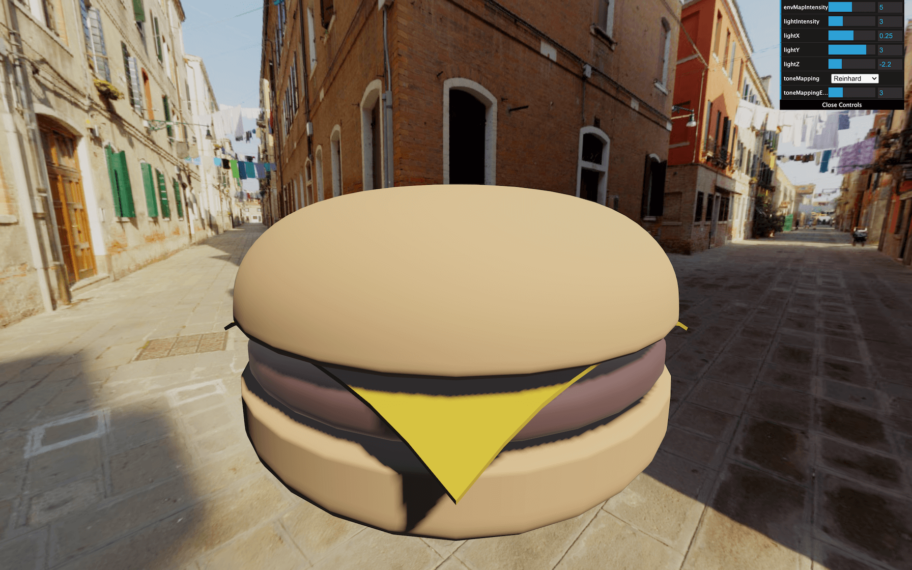
Now you get a very decent, acne-free hamburger.
Bon appétit.