26 Raging sea
Difficulty Hard
Introduction
Now that we know how to use shaders and draw some patterns let’s make fair use of it and create a raging sea.
We are going to animate the waves and keep control of the parameters with the debug panel.
Setup
For now, all we have is a rotated plane using MeshBasicMaterial. The geometry has a 128x128 subdivision. We are going to animate the vertices to get the waves and we need quite a lot of vertices. 128x128 might not be enough, but we will increase the value if required.
Base
Let’s replace the material by a ShaderMaterial:
const waterMaterial = new THREE.ShaderMaterial()
JavaScript
Copy
Our Webpack configuration already supports GLSL files, but we need to create these files.
Create the vertex shader in /src/shaders/water/vertex.glsl :
void main()
{
    vec4 modelPosition = modelMatrix * vec4(position, 1.0);
    vec4 viewPosition = viewMatrix * modelPosition;
    vec4 projectedPosition = projectionMatrix * viewPosition;
    gl_Position = projectedPosition;
}
GLSL
Copy
Now create the fragment shader in /src/shaders/water/fragment.glsl :
void main()
{
    gl_FragColor = vec4(0.5, 0.8, 1.0, 1.0);
}
GLSL
Copy
Finally, import those shaders in your script and use them in a ShaderMaterial:
// ...

import waterVertexShader from './shaders/water/vertex.glsl'
import waterFragmentShader from './shaders/water/fragment.glsl'

// ...

const waterMaterial = new THREE.ShaderMaterial({
    vertexShader: waterVertexShader,
    fragmentShader: waterFragmentShader
})
JavaScript
Copy
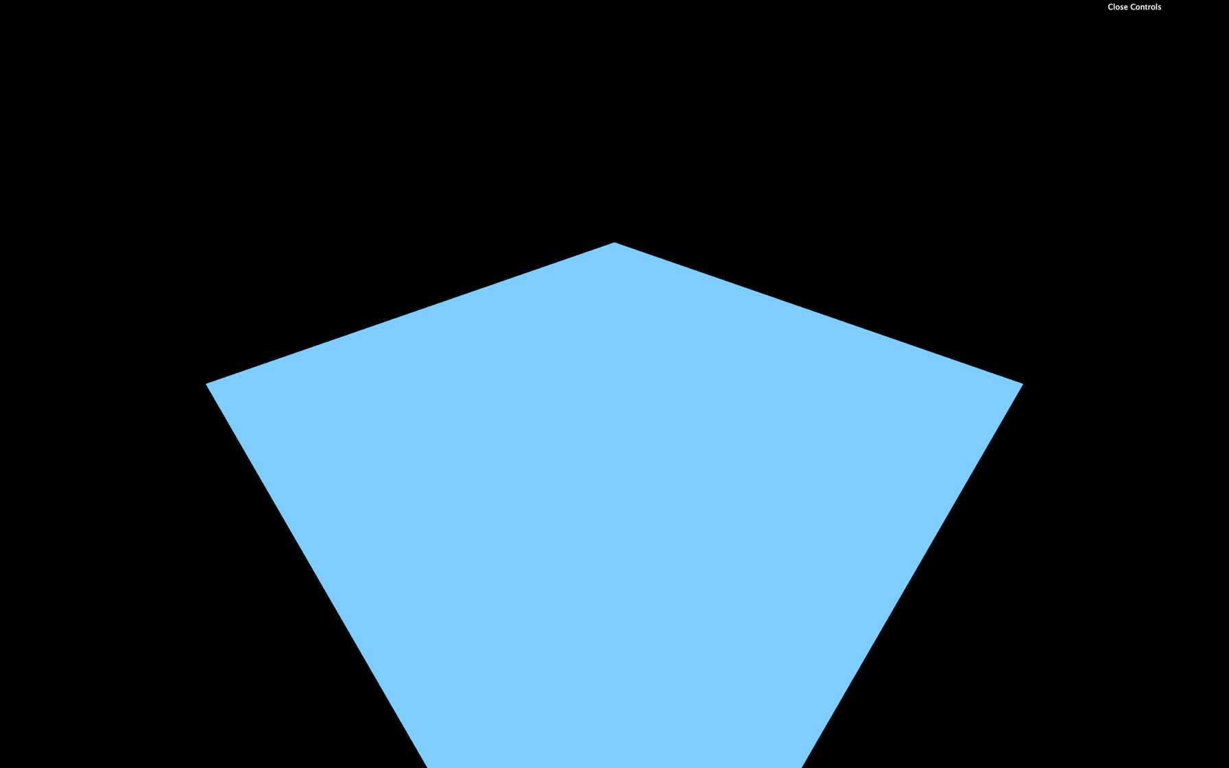
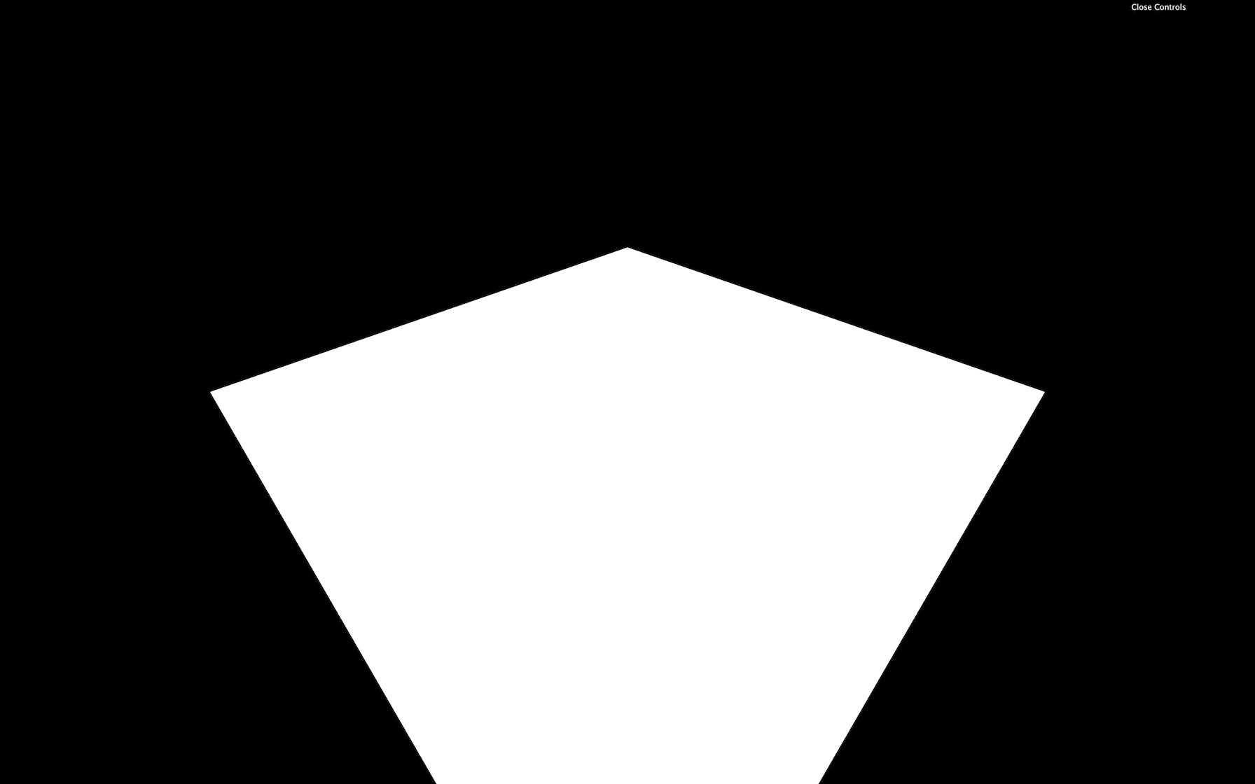
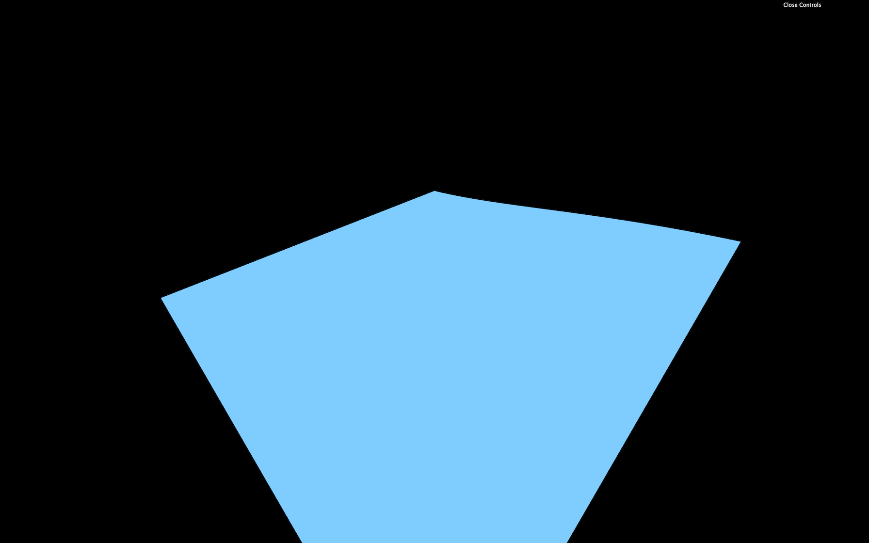
You should get a blue plane. If not, check the logs.
If you did all of this from memory, congratulation, you are a genius. If not, it’s perfectly normal, and you only need time.
Big waves
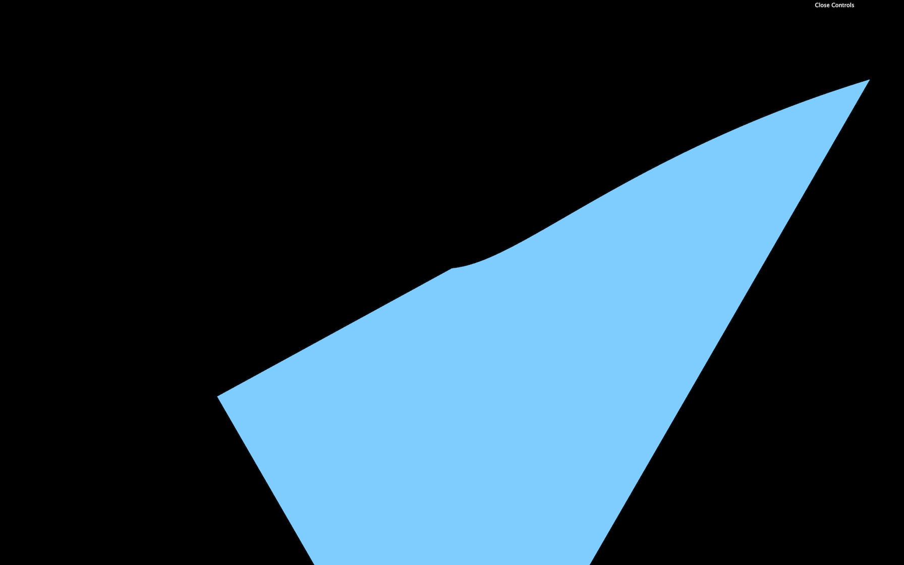
We begin with the big waves to get significant results quickly. What’s better than a sinus to create waves?
In the vertex shader, let’s move the y value of the modelPosition with a sin(...) based on the x :
vec4 modelPosition = modelMatrix * vec4(position, 1.0);
modelPosition.y += sin(modelPosition.x);
GLSL
Copy
The displacement and frequency should be way too high. Instead of just multiplying the values numbers coming out from nowhere in the shader, we will use uniforms to have more control over them.
Let’s start with the elevation.
Elevation
Add a uBigWavesElevation uniform to the ShaderMaterial:
const waterMaterial = new THREE.ShaderMaterial({
    vertexShader: waterVertexShader,
    fragmentShader: waterFragmentShader,
    uniforms:
    {
        uBigWavesElevation: { value: 0.2 }
    }
})
JavaScript
Copy
We can now retrieve and use the uBigWavesElevation uniform in the vertex shader:
uniform float uBigWavesElevation;

void main()
{
    // ...
    modelPosition.y += sin(modelPosition.x) * uBigWavesElevation;

    // ...
}
GLSL
Copy
Instead of updating the y property directly, we should use a variable named elevation . This will get handy later when we are going to color those waves:
uniform float uBigWavesElevation;

void main()
{
    vec4 modelPosition = modelMatrix * vec4(position, 1.0);

    // Elevation
    float elevation = sin(modelPosition.x) * uBigWavesElevation;
    modelPosition.y += elevation;

    // ...
}
GLSL
Copy
Because the elevation is now handled in the JavaScript, we can add it to our Dat.GUI:
gui.add(waterMaterial.uniforms.uBigWavesElevation, 'value').min(0).max(1).step(0.001).name('uBigWavesElevation')
JavaScript
Copy
Frequency
We can now take care of the frequency. Currently, the waves elevation only changes on the x axis but it would be even better to control both x and z axes.
Create a uBigWavesFrequency uniform with a Vector2:
const waterMaterial = new THREE.ShaderMaterial({
    vertexShader: waterVertexShader,
    fragmentShader: waterFragmentShader,
    uniforms:
    {
        uBigWavesElevation: { value: 0.2 },
        uBigWavesFrequency: { value: new THREE.Vector2(4, 1.5) }
    }
})
JavaScript
Copy
In the vertex shader, retrieve the uniform —be careful, it’s a vec2 — and apply it in the sin(...) with only the x property to begin with:
// ...
uniform vec2 uBigWavesFrequency;

void main()
{
    // ...

    float elevation = sin(modelPosition.x * uBigWavesFrequency.x) * uBigWavesElevation;

    // ...
}
GLSL
Copy
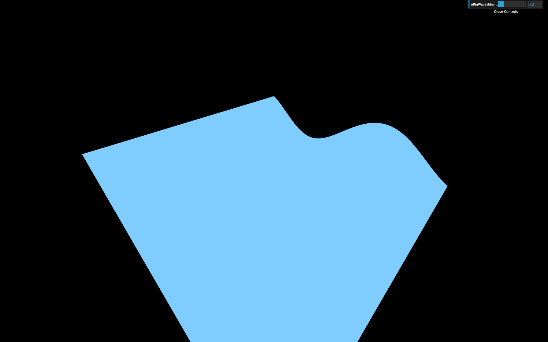
This should result in more waves because the frequency is higher.
Let’s use the second value of the uBigWavesFrequency ( y ) to control the waves on the z axis. We can do that by multiplying the first sin(...) by another sin(...) :
float elevation = sin(modelPosition.x * uBigWavesFrequency.x) * sin(modelPosition.z * uBigWavesFrequency.y) * uBigWavesElevation;
GLSL
Copy
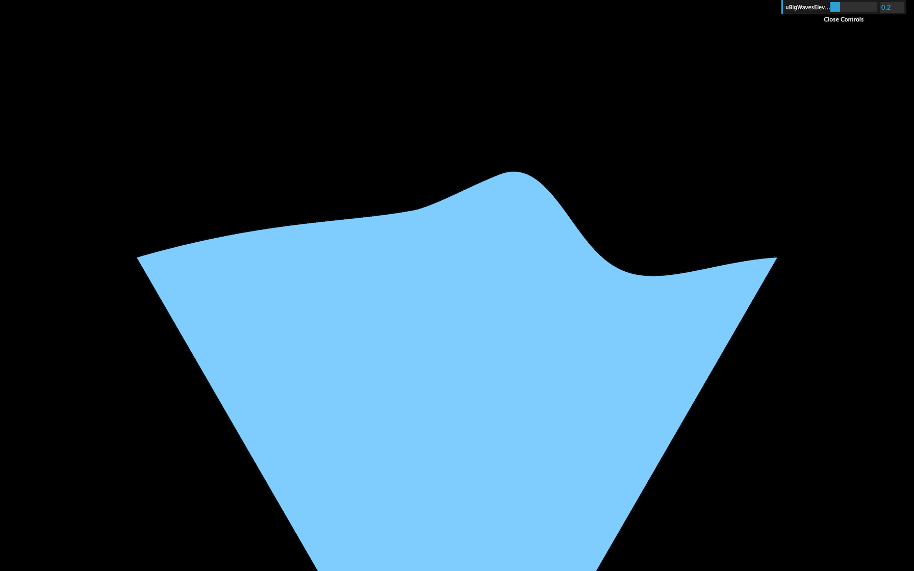
You should get waves on the z axis too.
We can now add those x and y properties to our Dat.GUI:
gui.add(waterMaterial.uniforms.uBigWavesFrequency.value, 'x').min(0).max(10).step(0.001).name('uBigWavesFrequencyX')
gui.add(waterMaterial.uniforms.uBigWavesFrequency.value, 'y').min(0).max(10).step(0.001).name('uBigWavesFrequencyY')
JavaScript
Copy
Animate
Let’s animate these big waves. We are going to use the elapsed time as we did in a previous lesson to offset the value in the sin(...) and create the animation.
First, create a uTime uniform in the ShaderMaterial:
const waterMaterial = new THREE.ShaderMaterial({
    // ...
    uniforms:
    {
        uTime: { value: 0 },
        // ...
    }
})
JavaScript
Copy
Then, update the value in the tick function :
const clock = new THREE.Clock()

const tick = () =>
{
    const elapsedTime = clock.getElapsedTime()

    // Water
    waterMaterial.uniforms.uTime.value = elapsedTime

    // ...
}
JavaScript
Copy
In the vertex shader, retrieve and use the uTime in both sin(...) functions:
uniform float uTime;
// ...

void main()
{
    // ...

    float elevation = sin(modelPosition.x * uBigWavesFrequency.x + uTime) * sin(modelPosition.z * uBigWavesFrequency.y + uTime) * uBigWavesElevation;

    // ...
}
GLSL
Copy
You now get animated waves. While the speed is ok for a raging sea, it would be great to be able to control it.
Let’s create a uBigWavesSpeed uniform and multiply our uTime by it. We will use a float to make it more simple, but if you want to control both axes speed separately, you can use a vec2 .
Create the uBigWavesSpeed uniform in the ShaderMaterial and add the tweak:
const waterMaterial = new THREE.ShaderMaterial({
    // ...
    uniforms:
    {
        // ...
        uBigWavesSpeed: { value: 0.75 }
    }
})

// ...
gui.add(waterMaterial.uniforms.uBigWavesSpeed, 'value').min(0).max(4).step(0.001).name('uBigWavesSpeed')
JavaScript
Copy
In the vertex shader, retrieve the uBigWavesSpeed uniform and multiply the uTime by it in both sin(...) functions:
// ...
uniform float uBigWavesSpeed;

void main()
{
    // ...

    float elevation = sin(modelPosition.x * uBigWavesFrequency.x + uTime * uBigWavesSpeed) * sin(modelPosition.z * uBigWavesFrequency.y + uTime * uBigWavesSpeed) * uBigWavesElevation;

    // ...
}
GLSL
Copy
Our elevation formula is taking way too long. Don’t hesitate to refactor a little by using variables or simple line breaks:
float elevation = sin(modelPosition.x * uBigWavesFrequency.x + uTime * uBigWavesSpeed) *
                  sin(modelPosition.z * uBigWavesFrequency.y + uTime * uBigWavesSpeed) *
                  uBigWavesElevation;
GLSL
Copy
Colors
Our waves are starting to look great, but that uniform blue color doesn’t help.
Let’s produce two colors, one for the depth and one for the surface. If you remember, adding Three.js colors to Dat.GUI is a little complicated.
First, we need to create a debugObject right after the gui instantiation:
const gui = new dat.GUI({ width: 340 })
const debugObject = {}
JavaScript
Copy
Then, right before the waterMaterial instantiation, we can create these two colors as properties of debugObject , and use them in two new uniforms that we will call uDepthColor and uSurfaceColor . These colors will be using the Color class:
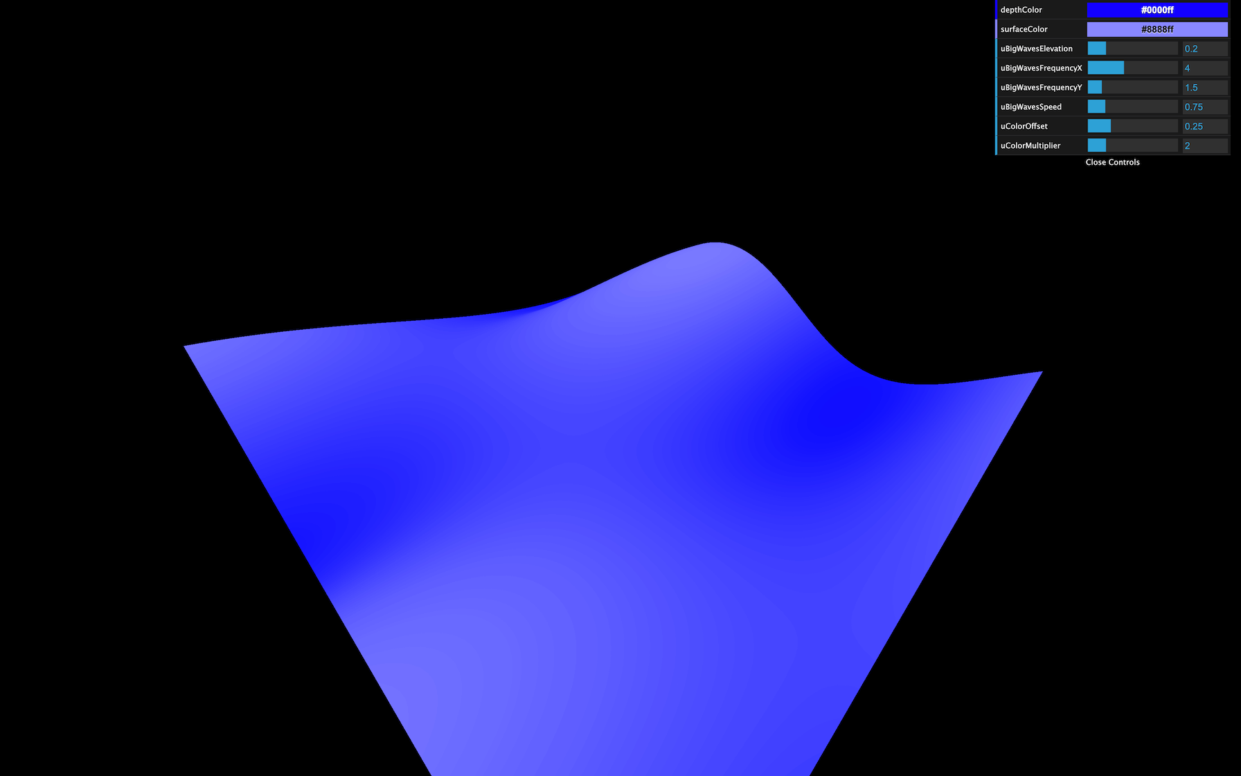
// Colors
debugObject.depthColor = '#0000ff'
debugObject.surfaceColor = '#8888ff'

// Material
const waterMaterial = new THREE.ShaderMaterial({
    vertexShader: waterVertexShader,
    fragmentShader: waterFragmentShader,
    uniforms:
    {
        // ...
        uDepthColor: { value: new THREE.Color(debugObject.depthColor) },
        uSurfaceColor: { value: new THREE.Color(debugObject.surfaceColor) }
    }
})
JavaScript
Copy
We can then add them to our Dat.GUI with the addColor method. We also need to update the waterMaterial uniforms when the color changes with onChange(...) :
debugObject.depthColor = '#0000ff'
debugObject.surfaceColor = '#8888ff'

gui.addColor(debugObject, 'depthColor').onChange(() => { waterMaterial.uniforms.uDepthColor.value.set(debugObject.depthColor) })
gui.addColor(debugObject, 'surfaceColor').onChange(() => { waterMaterial.uniforms.uSurfaceColor.value.set(debugObject.surfaceColor) })
JavaScript
Copy
You should see the color tweaks, but changing them doesn’t affect the material. That is because we haven’t use the uDepthColor and uSurfaceColor uniforms in our shader yet.
In the fragment shader, start by retrieving these colors:
uniform vec3 uDepthColor;
uniform vec3 uSurfaceColor;
GLSL
Copy
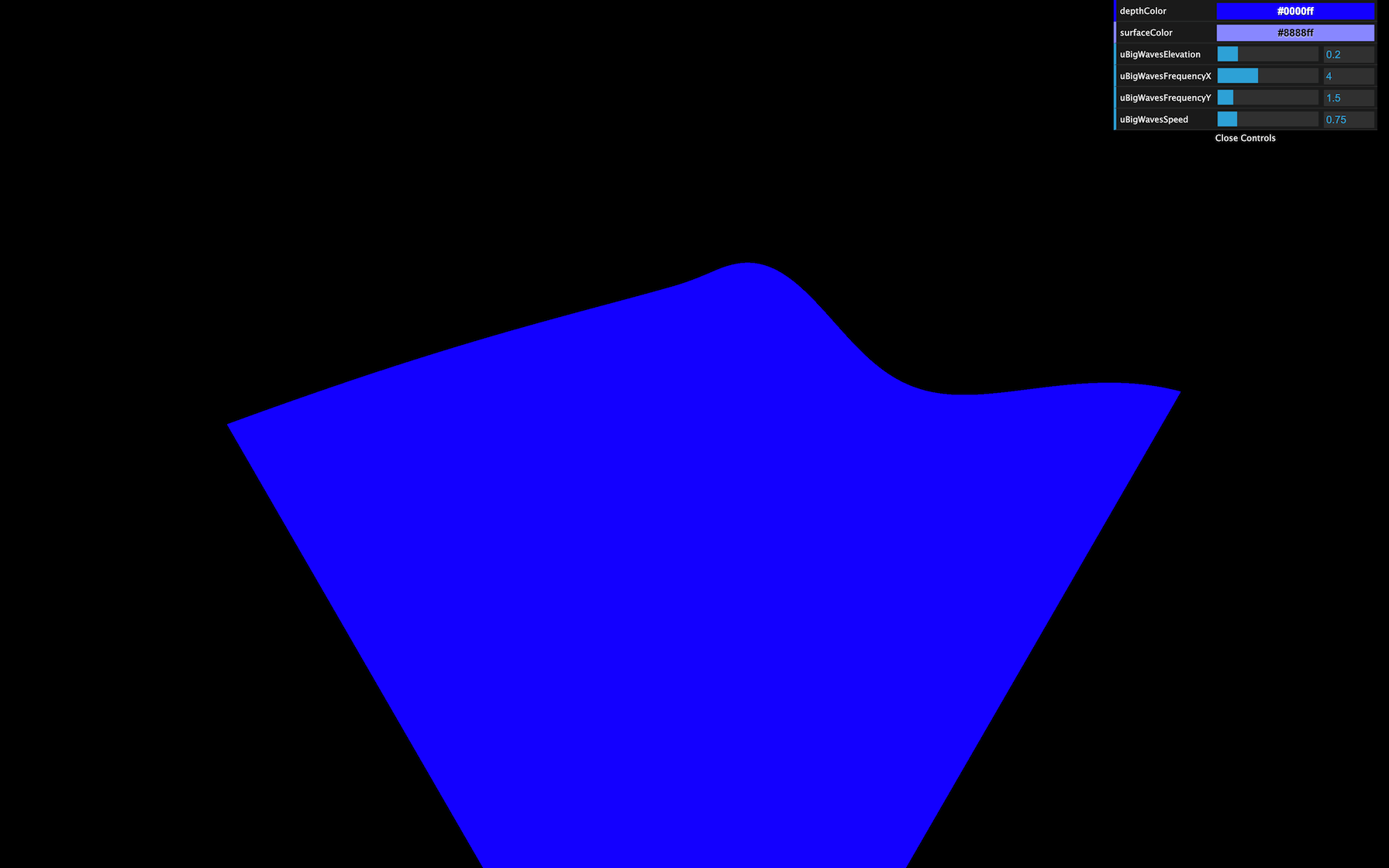
And use only one color to verify that everything is working:
// ...

void main()
{
    gl_FragColor = vec4(uDepthColor, 1.0);
}
GLSL
Copy
What we need to do now is use more of the uDepthColor if the wave is low and more of the uSurfaceColor if it is high.
Remember the previous lesson, we are going to use the mix(...) . This function needs a first input, a second input, and a value that will dictate how to mix these two first inputs.
- If that third value is
0.0, the result will be the first input. - If that third value is
1.0, the result will be the second input. - If that third value is
0.5, the result will be a perfect mix of the two inputs. - If that third value is below
0.0or above1.0the value will be extrapolated.
The two first parameters are, as you can imagine, the uDepthColor and the uSurfaceColor . But what about the third value that controls the mix?
We could use the elevation , unfortunately this variable is in the vertex shader.
To transmit this variable to the fragment shader —like we did in the previous lessons— we are going to use a varying . In the vertex shader, create a vElevation varying and update it in the main function:
// ...

varying float vElevation;

void main()
{
    // ...

    // Varyings
    vElevation = elevation;
}
GLSL
Copy
In the fragment shader, retrieve the varying. Then create a color variable that mixes the uDepthColor and the uSurfaceColor according to the vElevation :
uniform vec3 uDepthColor;
uniform vec3 uSurfaceColor;

varying float vElevation;

void main()
{
    vec3 color = mix(uDepthColor, uSurfaceColor, vElevation);
    gl_FragColor = vec4(color, 1.0);
}
GLSL
Copy
You should see a very slight variation in the color. The problem is that our vElevation currently only goes from - 0.2 to + 0.2 according to our code. We need to find a way to control this vElevation , but only in the fragment shader.
Let’s add some uniforms! We will create a uColorOffset and uColorMultiplier , and add both of them to our Dat.GUI:
const waterMaterial = new THREE.ShaderMaterial({
    vertexShader: waterVertexShader,
    fragmentShader: waterFragmentShader,
    uniforms:
    {
        // ...
        uColorOffset: { value: 0.25 },
        uColorMultiplier: { value: 2 },
    }
})

// ...
gui.add(waterMaterial.uniforms.uColorOffset, 'value').min(0).max(1).step(0.001).name('uColorOffset')
gui.add(waterMaterial.uniforms.uColorMultiplier, 'value').min(0).max(10).step(0.001).name('uColorMultiplier')
JavaScript
Copy
Now retrieve the uColorOffset and uColorMultiplier uniforms in the fragment shader, create a mixStrength variable —to make it easier to read— based on these two uniforms, and use that variable in the mix(...) function:
uniform vec3 uDepthColor;
uniform vec3 uSurfaceColor;
uniform float uColorOffset;
uniform float uColorMultiplier;

varying float vElevation;

void main()
{
    float mixStrength = (vElevation + uColorOffset) * uColorMultiplier;
    vec3 color = mix(uDepthColor, uSurfaceColor, mixStrength);

    gl_FragColor = vec4(color, 1.0);
}
GLSL
Copy
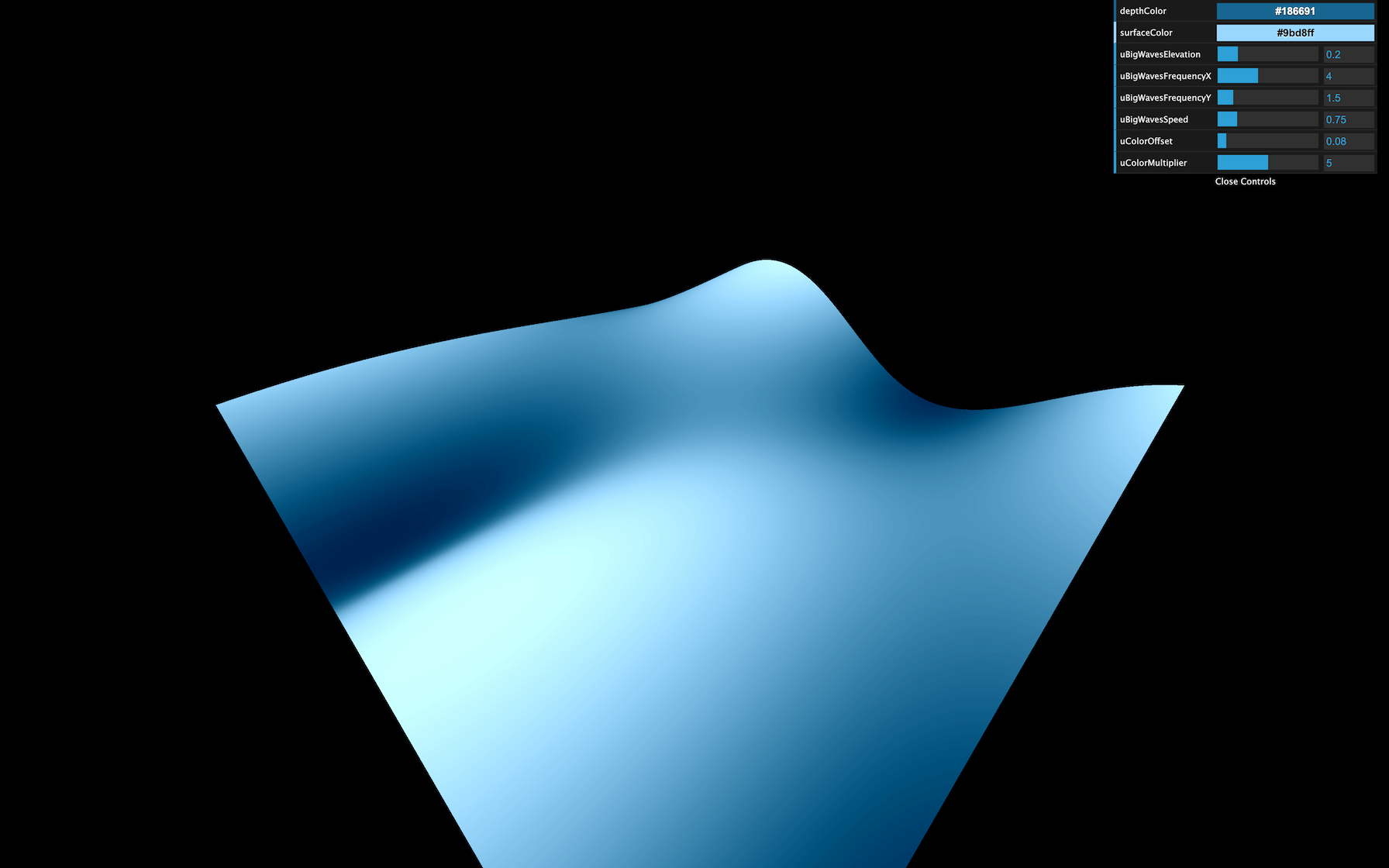
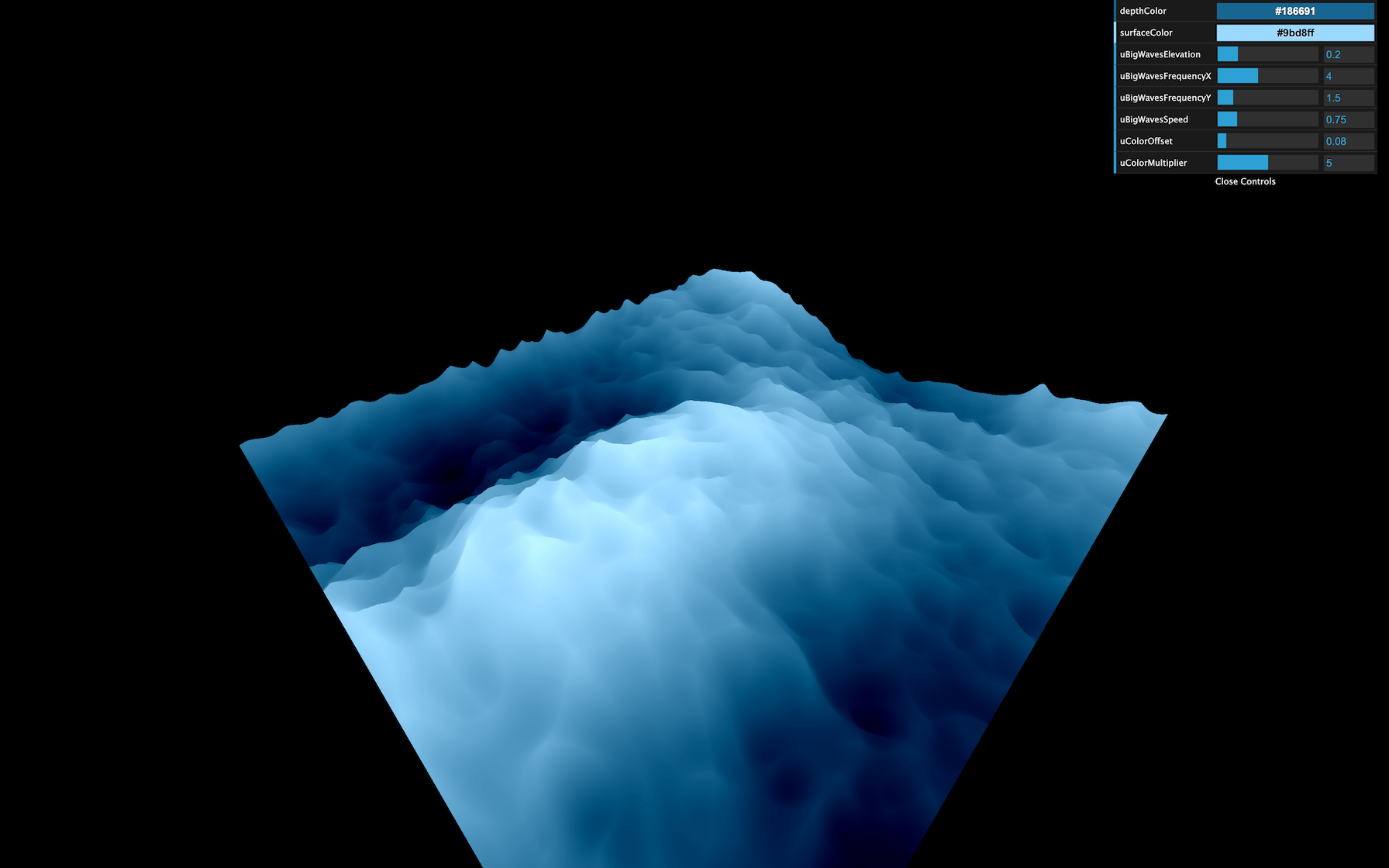
You obtain a much better gradient. Tweak the values to secure colors you like:
debugObject.depthColor = '#186691'
debugObject.surfaceColor = '#9bd8ff'

// ...

const waterMaterial = new THREE.ShaderMaterial({
    vertexShader: waterVertexShader,
    fragmentShader: waterFragmentShader,
    uniforms:
    {
        // ...

        uColorOffset: { value: 0.08 },
        uColorMultiplier: { value: 5 }
    }
})
GLSL
Copy
Small waves
For the small waves, we are going to use a perlin noise. We used a 2D perlin noise in the previous lesson, where we sent 2D coordinates and got a float value in return. This time, we are going to use a 3D perlin. That will enable variations of that noise in time for a more realistic result.
Go to the same gist as during the previous lesson and copy the Classic Perlin 3D Noise by Stefan Gustavson : https://gist.github.com/patriciogonzalezvivo/670c22f3966e662d2f83
Or copy the code below to the vertex shader:
// Classic Perlin 3D Noise
// by Stefan Gustavson
//
vec4 permute(vec4 x)
{
    return mod(((x*34.0)+1.0)*x, 289.0);
}
vec4 taylorInvSqrt(vec4 r)
{
    return 1.79284291400159 - 0.85373472095314 * r;
}
vec3 fade(vec3 t)
{
    return t*t*t*(t*(t*6.0-15.0)+10.0);
}

float cnoise(vec3 P)
{
    vec3 Pi0 = floor(P); // Integer part for indexing
    vec3 Pi1 = Pi0 + vec3(1.0); // Integer part + 1
    Pi0 = mod(Pi0, 289.0);
    Pi1 = mod(Pi1, 289.0);
    vec3 Pf0 = fract(P); // Fractional part for interpolation
    vec3 Pf1 = Pf0 - vec3(1.0); // Fractional part - 1.0
    vec4 ix = vec4(Pi0.x, Pi1.x, Pi0.x, Pi1.x);
    vec4 iy = vec4(Pi0.yy, Pi1.yy);
    vec4 iz0 = Pi0.zzzz;
    vec4 iz1 = Pi1.zzzz;

    vec4 ixy = permute(permute(ix) + iy);
    vec4 ixy0 = permute(ixy + iz0);
    vec4 ixy1 = permute(ixy + iz1);

    vec4 gx0 = ixy0 / 7.0;
    vec4 gy0 = fract(floor(gx0) / 7.0) - 0.5;
    gx0 = fract(gx0);
    vec4 gz0 = vec4(0.5) - abs(gx0) - abs(gy0);
    vec4 sz0 = step(gz0, vec4(0.0));
    gx0 -= sz0 * (step(0.0, gx0) - 0.5);
    gy0 -= sz0 * (step(0.0, gy0) - 0.5);

    vec4 gx1 = ixy1 / 7.0;
    vec4 gy1 = fract(floor(gx1) / 7.0) - 0.5;
    gx1 = fract(gx1);
    vec4 gz1 = vec4(0.5) - abs(gx1) - abs(gy1);
    vec4 sz1 = step(gz1, vec4(0.0));
    gx1 -= sz1 * (step(0.0, gx1) - 0.5);
    gy1 -= sz1 * (step(0.0, gy1) - 0.5);

    vec3 g000 = vec3(gx0.x,gy0.x,gz0.x);
    vec3 g100 = vec3(gx0.y,gy0.y,gz0.y);
    vec3 g010 = vec3(gx0.z,gy0.z,gz0.z);
    vec3 g110 = vec3(gx0.w,gy0.w,gz0.w);
    vec3 g001 = vec3(gx1.x,gy1.x,gz1.x);
    vec3 g101 = vec3(gx1.y,gy1.y,gz1.y);
    vec3 g011 = vec3(gx1.z,gy1.z,gz1.z);
    vec3 g111 = vec3(gx1.w,gy1.w,gz1.w);

    vec4 norm0 = taylorInvSqrt(vec4(dot(g000, g000), dot(g010, g010), dot(g100, g100), dot(g110, g110)));
    g000 *= norm0.x;
    g010 *= norm0.y;
    g100 *= norm0.z;
    g110 *= norm0.w;
    vec4 norm1 = taylorInvSqrt(vec4(dot(g001, g001), dot(g011, g011), dot(g101, g101), dot(g111, g111)));
    g001 *= norm1.x;
    g011 *= norm1.y;
    g101 *= norm1.z;
    g111 *= norm1.w;

    float n000 = dot(g000, Pf0);
    float n100 = dot(g100, vec3(Pf1.x, Pf0.yz));
    float n010 = dot(g010, vec3(Pf0.x, Pf1.y, Pf0.z));
    float n110 = dot(g110, vec3(Pf1.xy, Pf0.z));
    float n001 = dot(g001, vec3(Pf0.xy, Pf1.z));
    float n101 = dot(g101, vec3(Pf1.x, Pf0.y, Pf1.z));
    float n011 = dot(g011, vec3(Pf0.x, Pf1.yz));
    float n111 = dot(g111, Pf1);

    vec3 fade_xyz = fade(Pf0);
    vec4 n_z = mix(vec4(n000, n100, n010, n110), vec4(n001, n101, n011, n111), fade_xyz.z);
    vec2 n_yz = mix(n_z.xy, n_z.zw, fade_xyz.y);
    float n_xyz = mix(n_yz.x, n_yz.y, fade_xyz.x);
    return 2.2 * n_xyz;
}
GLSL
Copy
No fix needed this time.
We can now use the cnoise function with a vec3 as parameter.
Here are the three values of the vec3 :
-
xwill be thexofmodelPosition -
ywill be thezofmodelPosition -
zwill beuTime. That third value will make the noise evolve in a natural and realistic style.
elevation += cnoise(vec3(modelPosition.xz, uTime));
GLSL
Copy
This is not the expected result. First, the waves speed is too fast. So you must multiply the uTime by 0.2 :
elevation += cnoise(vec3(modelPosition.xz, uTime * 0.2));
GLSL
Copy
Secondly, the frequency is too small. That results in waves as large as the big ones we created previously. To increase the frequency, multiply modelPosition.xz by 3.0 :
elevation += cnoise(vec3(modelPosition.xz * 3.0, uTime * 0.2));
GLSL
Copy
Thirdly, the waves are way too high. Let’s reduce that by multiplying the noise by 0.15 :
elevation += cnoise(vec3(modelPosition.xz * 3.0, uTime * 0.2)) * 0.15;
GLSL
Copy
Finally, real-life waves aren’t that smooth. Realistic waves have rounded troughs and high crests. To achieve this result, we can use the abs(...) function:
elevation += abs(cnoise(vec3(modelPosition.xz * 3.0, uTime * 0.2)) * 0.15);
GLSL
Copy
We got exactly the opposite of what we wanted with rounded crests and high troughs. To invert the waves, replace + by - :
elevation -= abs(cnoise(vec3(modelPosition.xz * 3.0, uTime * 0.2)) * 0.15);
GLSL
Copy
That’s better, but when you look at waves in a raging sea, they seem more chaotic with different and unpredictable frequencies.
We need to apply even more noises at higher frequencies. We could repeat the previous line with different values, but it’s the perfect occasion to use a for(...) loop.
for(...) loops work in GLSL. Just make sure to user a float type variable. We are going to use 3 iterations starting from 1.0 :
for(float i = 1.0; i <= 3.0; i++)
{
}
GLSL
Copy
Then move our previous formula in the loop:
for(float i = 1.0; i <= 3.0; i++)
{
    elevation -= abs(cnoise(vec3(modelPosition.xz * 3.0, uTime * 0.2)) * 0.15);
}
GLSL
Copy
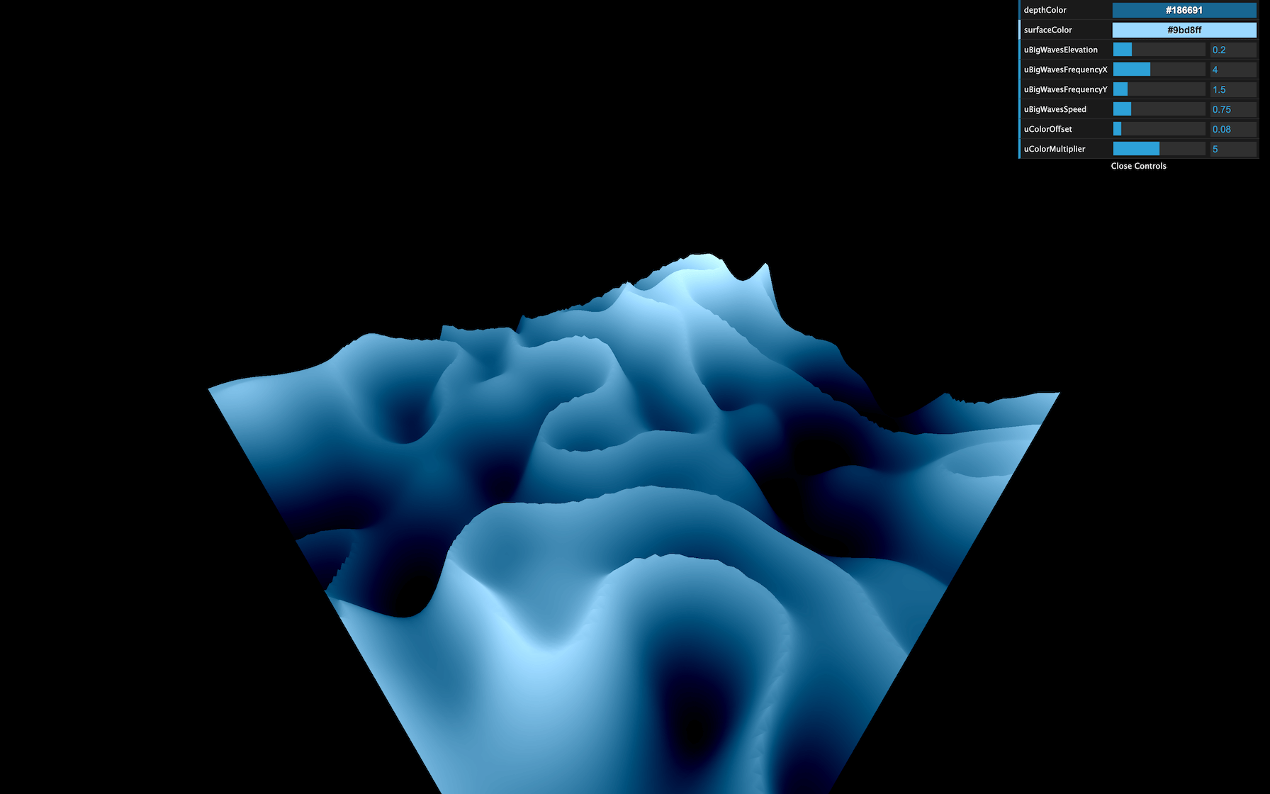
Right now, we are applying 3 times the same formula, which should result in the same waves, but their amplitude is much more prominent.
Let’s increase the frequency and reduce the amplitude according to the i variable:
for(float i = 1.0; i <= 3.0; i++)
{
    elevation -= abs(cnoise(vec3(modelPosition.xz * 3.0 * i, uTime * 0.2)) * 0.15 / i);
}
GLSL
Copy
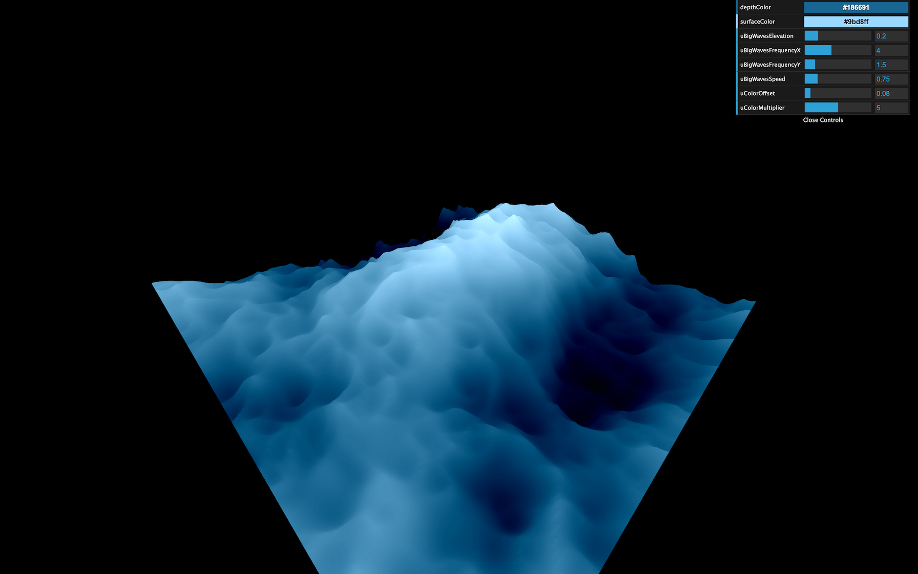
That’s much better. Maybe you haven’t noticed it, but we can barely see the smaller waves. That is because our geometry is missing vertices. Increase the subdivisions to 512x512 :
const waterGeometry = new THREE.PlaneBufferGeometry(2, 2, 512, 512)
GLSL
Copy
That represents a lot of triangles, but the plane is the only geometry we have in the scene, and we are animating almost everything in the shader, meaning that the GPU is doing the heavy lifting.
Let’s add some uniforms and tweaks to control these small waves:
const waterMaterial = new THREE.ShaderMaterial({
    vertexShader: waterVertexShader,
    fragmentShader: waterFragmentShader,
    uniforms:
    {
        // ...

        uSmallWavesElevation: { value: 0.15 },
        uSmallWavesFrequency: { value: 3 },
        uSmallWavesSpeed: { value: 0.2 },
        uSmallIterations: { value: 4 },

        // ...
    }
})

// ...

gui.add(waterMaterial.uniforms.uSmallWavesElevation, 'value').min(0).max(1).step(0.001).name('uSmallWavesElevation')
gui.add(waterMaterial.uniforms.uSmallWavesFrequency, 'value').min(0).max(30).step(0.001).name('uSmallWavesFrequency')
gui.add(waterMaterial.uniforms.uSmallWavesSpeed, 'value').min(0).max(4).step(0.001).name('uSmallWavesSpeed')
gui.add(waterMaterial.uniforms.uSmallIterations, 'value').min(0).max(5).step(1).name('uSmallIterations')
JavaScript
Copy
And in the vertex shader:
uniform float uSmallWavesElevation;
uniform float uSmallWavesFrequency;
uniform float uSmallWavesSpeed;
uniform float uSmallIterations;

// ...

void main()
{
    // ...

    for(float i = 1.0; i <= uSmallIterations; i++)
    {
        elevation -= abs(cnoise(vec3(modelPosition.xz * uSmallWavesFrequency * i, uTime * uSmallWavesSpeed)) * uSmallWavesElevation / i);
    }

    // ...
}
GLSL
Copy
And that’s it.
Go further
If you wanted to go further, you could try to add foam.
You could also attempt to enlarge the plane.
Adding fog would be a great way to get a more immersive experience that would enhance the feeling of being lost in the sea. Be careful though, adding fog will be more challenging than what we saw because you need to write the code for that fog on your own.
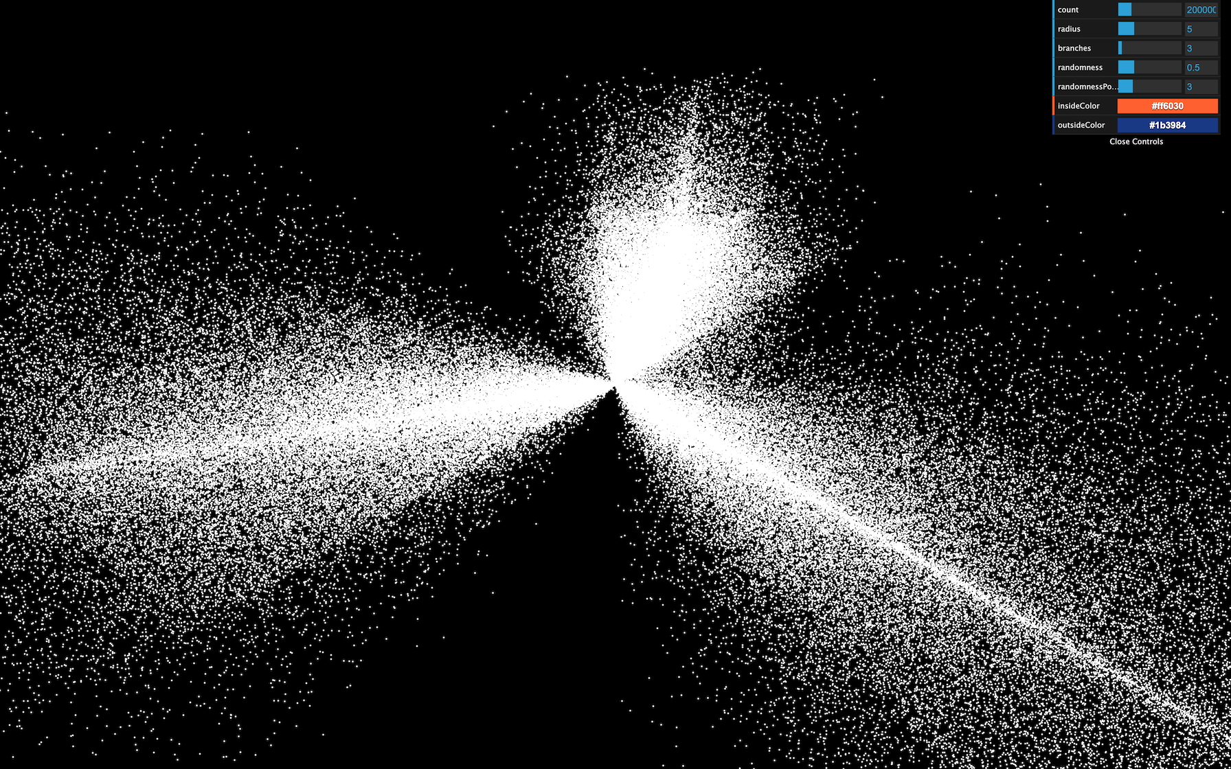
27 Animated galaxy
Difficulty Very hard
Introduction
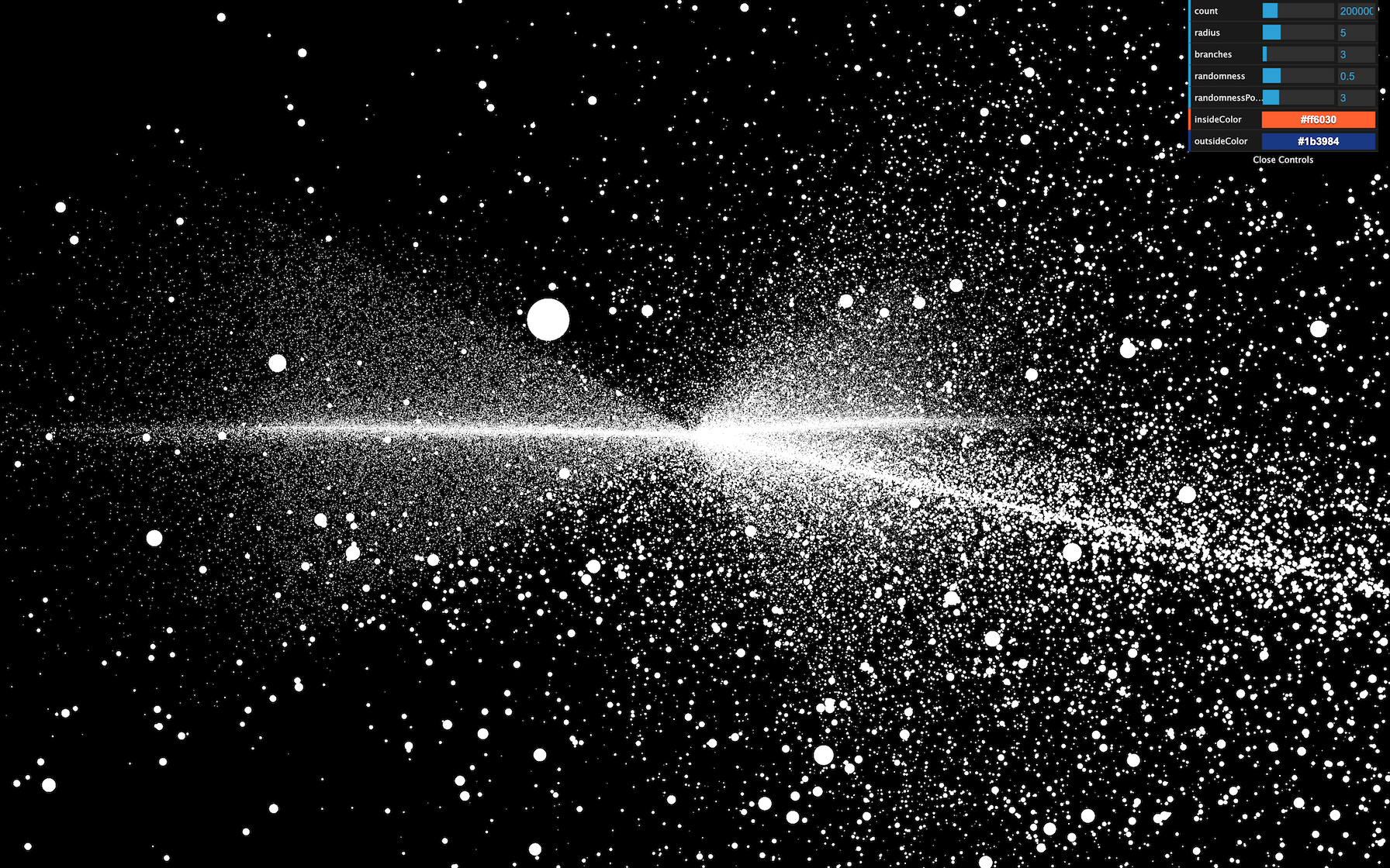
You can also use shaders with the particles. As we saw in the Particles lesson, animating each vertex of the geometry isn’t an efficient solution for performance reasons. That is where the GPU comes in by animating those vertices directly in the vertex shader.
In this lesson, we are going to start with our particle galaxy. We will animate the particles in the vertex shader to make the stars rotate but at different speeds depending on the center’s distance, and we will draw a pattern in the particles instead of those ugly squares.
Setup
The starter is almost the same as the Galaxy Generator lesson starter. The only difference is the spin formula is missing because we will do the spin animation in the shader.

Replacing PointsMaterial by ShaderMaterial
The particles are currently using a PointsMaterial, but we need to use a ShaderMaterial if we want to write our own shaders.
Replace PointsMaterial by ShaderMaterial :
material = new THREE.ShaderMaterial({
    // ...
})
JavaScript
Copy
If you look at the logs, you should see two warnings telling us that the ShaderMaterial supports neither size nor sizeAttenuation . We will have to add these features on our own. For now, remove these properties:
material = new THREE.ShaderMaterial({
    depthWrite: false,
    blending: THREE.AdditiveBlending,
    vertexColors: true
})
JavaScript
Copy
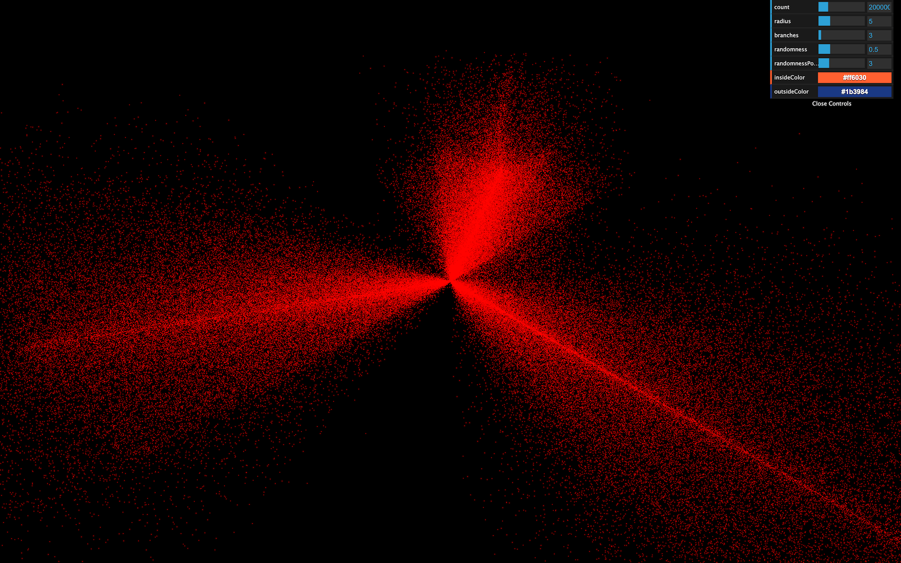
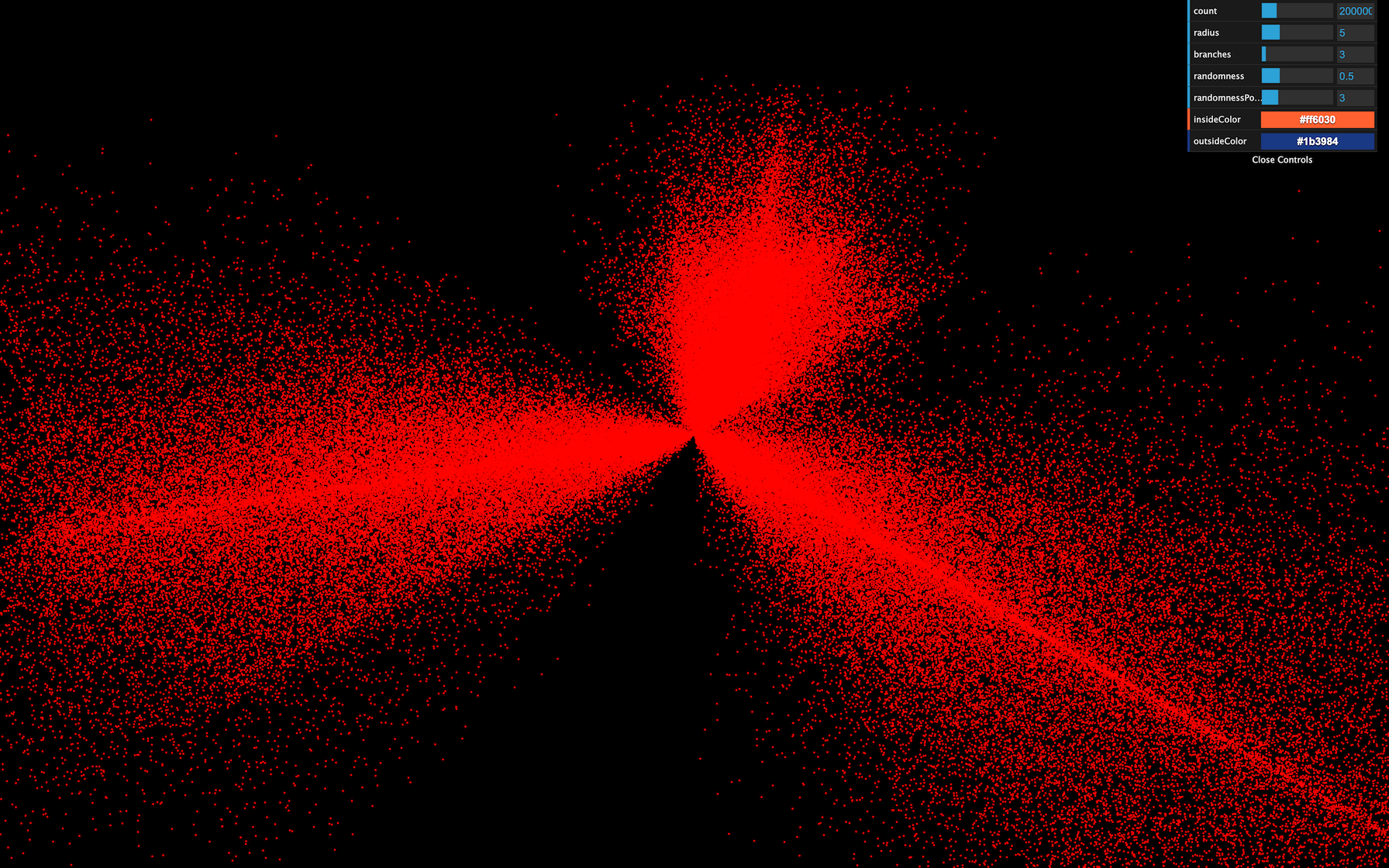
At this exact moment, some might see the particles like tiny red dots, and some might get a black screen. That depends on how your GPU handles the particles when no size is provided. We won’t waste time on this because we will give a size anyway, and everyone should see the particles.
Clearly, we need to provide our own shaders. Add the following vertexShader :
material = new THREE.ShaderMaterial({

    // ...

    vertexShader: `
        void main()
        {
            /**
             * Position
             */
            vec4 modelPosition = modelMatrix * vec4(position, 1.0);
            vec4 viewPosition = viewMatrix * modelPosition;
            vec4 projectedPosition = projectionMatrix * viewPosition;
            gl_Position = projectedPosition;

            /**
             * Size
             */
            gl_PointSize = 2.0;
        }
    `
})
JavaScript
Copy
The beginning of the shader is the same as we’ve already seen. We update the position by using successively the modelMatrix , the viewMatrix , and the projectionMatrix . But then, we assign a new variable called gl_PointSize with 2.0 as the value.
gl_PointSize is precisely what you might think. The particles will have a 2x2 size, and you should see 2x2 particles regardless of the distance of the camera.
The unit here are fragments and if you are using a normal screen with a pixel ratio of 1 , you’ll get 2 pixels by 2 pixels because 1 fragment = 1 pixel. But if you are using a screen with a higher pixel ratio like a retina screen, 1 fragment will be smaller than 1 pixel and you should get smaller particles. We’ll fix that later in order to get a consistent result through any pixel ratio.
Before we improve the particles size, let’s change the color.
The particles are currently red because we didn’t provide any fragmentShader and Three.js uses a default one with a red output.
Add the following fragment shader with a white color:
material = new THREE.ShaderMaterial({

        // ...

        fragmentShader: `
            void main()
            {
                gl_FragColor = vec4(1.0, 1.0, 1.0, 1.0);
            }
        `
    })
JavaScript
Copy
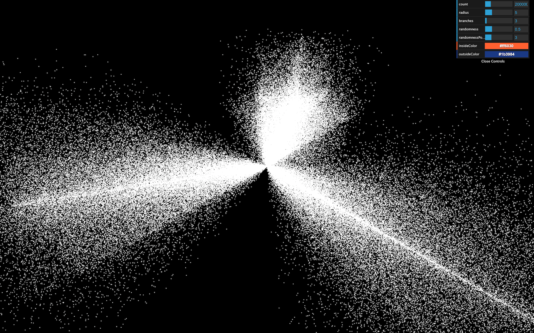
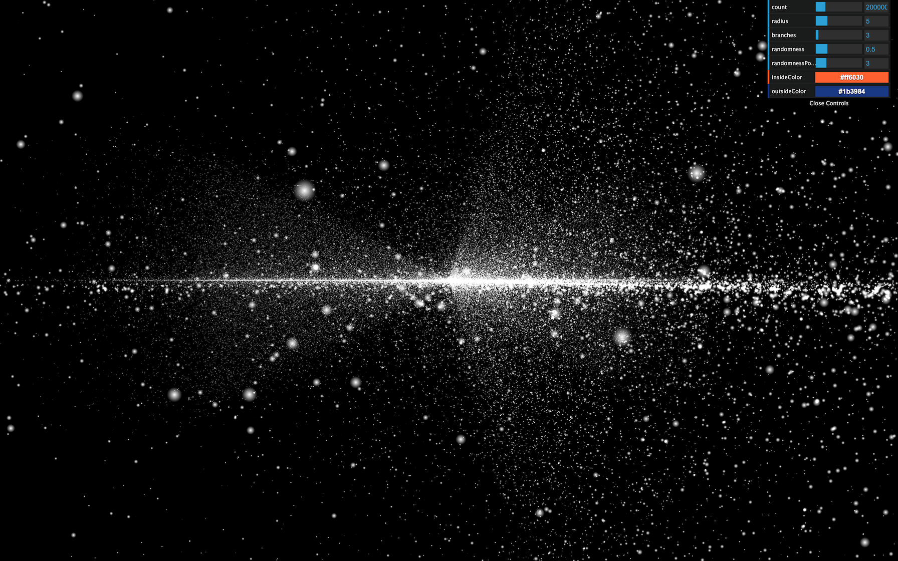
All the particles should be white.
Move the shaders to separate files
Now is an excellent time to move the shaders to separate files before they get too long and unmanageable.
In /src/ , create a shaders/ , and then a galaxy/ folder inside.
Inside that folder, create a vertex.glsl file with the vertexShader property content:
void main()
{
    /**
     * Position
     */
    vec4 modelPosition = modelMatrix * vec4(position, 1.0);
    vec4 viewPosition = viewMatrix * modelPosition;
    vec4 projectedPosition = projectionMatrix * viewPosition;
    gl_Position = projectedPosition;

    /**
     * Size
     */
    gl_PointSize = 2.0;
}
GLSL
Copy
And a fragment.glsl :
void main()
{
    gl_FragColor = vec4(1.0, 1.0, 1.0, 1.0);
}
GLSL
Copy
The Webpack configuration already supports .glsl files. We only need to import these in the JavaScript, and use them in the material:
import galaxyVertexShader from './shaders/galaxy/vertex.glsl'
import galaxyFragmentShader from './shaders/galaxy/fragment.glsl'

// ...

material = new THREE.ShaderMaterial({
    // ...

    vertexShader: galaxyVertexShader,
    fragmentShader: galaxyFragmentShader
})
JavaScript
Copy
The result should be the same.
You don’t need to put the shaders in separate files, but it’s good practice, and the syntax coloration might prevent you from making mistakes.
Also, if you installed a linter like suggested in a previous lesson, you’ll see potential errors before refreshing.
Handling the size
Base size
First, we will add a base size for every particles, and we want to be able to change the value from the JavaScript. To do that, let’s add the usual uniforms property to our material with a uSize uniform:
material = new THREE.ShaderMaterial({

    // ...

    uniforms:
    {
        uSize: { value: 8 }
    },

    // ...
})
JavaScript
Copy
We can now retrieve the value in the vertexShader and use it in the gl_PointSize :
uniform float uSize;

void main()
{
    // ...

    gl_PointSize = uSize;
}
GLSL
Copy
They appear quite big here, but they’ll look smaller very soon.
Randomized size
In real life, stars have different sizes. Let’s add some randomness. We want to associate a distinct value for each vertex. We are going to use an attribute.
Add a aScale attribute to the geometry. We already have a position , and a color attribute and we can easily add the new attribute following the same instructions:
geometry = new THREE.BufferGeometry()

const positions = new Float32Array(parameters.count * 3)
const colors = new Float32Array(parameters.count * 3)
const scales = new Float32Array(parameters.count * 1)

// ...

for(let i = 0; i < parameters.count; i++)
{
    // ...

    // Scale
    scales[i] = Math.random()
}

geometry.setAttribute('position', new THREE.BufferAttribute(positions, 3))
geometry.setAttribute('color', new THREE.BufferAttribute(colors, 3))
geometry.setAttribute('aScale', new THREE.BufferAttribute(scales, 1))
JavaScript
Copy
Make sure to use 1 instead of 3 when creating the Float32Array and the BufferAttribute because this value is a float and not a vec3 like the others —we need only one value per vertex. We also named the attribute aScale with a prepended a .
You might be tempted to change the position and color attributes for aPosition and aColor , but that would result in a bug because we are using a ShaderMaterial which pre-pend code to our vertex shader and that code add something like attribute vec3 position; and attribute vec3 color; .
We can now retrieve the attribute in the vertex shader and multiply the uSize by it:
uniform float uSize;

attribute float aScale;

void main()
{
    // ...

    gl_PointSize = uSize * aScale;
}
GLSL
Copy
You should see particles with random sizes.
Fixing the pixel ratio
However, we have a problem with our particles. Their size depends on the screen’s pixel ratio. Remember that we updated the pixel ratio of the renderer by using the following line:
renderer.setPixelRatio(Math.min(window.devicePixelRatio, 2))
JavaScript
Copy
If you have a screen with a pixel ratio of 1 , the particles will look 2 times bigger than if you had a screen with a pixel ratio of 2 .
We need a solution to get the same particle size regardless of the pixel ratio.
They are multiple ways of doing so. The easiest one is to multiply the uSize value by the pixel ratio of the renderer . We can retrieve this pixel ratio with the getPixelRatio() method:
material = new THREE.ShaderMaterial({

    // ...

    uniforms:
    {
        uSize: { value: 8 * renderer.getPixelRatio() }
    }

    // ...
})
JavaScript
Copy
Unhappily, this code won’t work because we are creating the material before we create the renderer . To fix that, simply move the first call of generateGalaxy after the instantiating the renderer :
/**
 * Renderer
 */
const renderer = new THREE.WebGLRenderer({
    canvas: canvas
})

// ...

/**
 * Generate the first galaxy
 */
generateGalaxy()
JavaScript
Copy

We now have particles that look the same regardless of the pixel ratio.
Size attenuation
We removed the property sizeAttenuation because the ShaderMaterial does not support it. We need to apply this size attenuation on our own.
As a reminder, the size attenuation makes the particles far from the camera smaller, and the ones close to the camera bigger. That simulates the perspective.
Instead of trying to guess the formula to get the right size, we will directly go to the Three.js dependency folder and get the code that handles this part in the PointsMaterial code.
While there is a lot of code in the Three.js library folder, it’s well organized and easy to navigate. Don’t hesitate to spend some time in it and get use to it.
You can find the shader handling this part in /node_modules/three/src/renderers/shaders/ShaderLib/point_vert.glsl.js and it should look like this:
#ifdef USE_SIZEATTENUATION

    bool isPerspective = isPerspectiveMatrix( projectionMatrix );

    if ( isPerspective ) gl_PointSize *= ( scale / - mvPosition.z );

#endif
GLSL
Copy
The only part we need is this one:
gl_PointSize *= ( scale / - mvPosition.z );
GLSL
Copy
To get the size attenuation, we need to multiply gl_PointSize by this formula ( scale / - mvPosition.z )
According to Three.js, the scale is a value related to the render height. To make things manageable, we can replace it with 1.0 .
The mvPosition corresponds to the position of the vertex once the modelMatrix and the viewMatrix have been applied. In our case, it’s our viewPosition variable.
This might sound a little complex, but we can write it like that:
gl_PointSize = uSize * aScale;
gl_PointSize *= (1.0 / - viewPosition.z);
GLSL
Copy

Get the camera close to the particles to see them getting bigger. We have our size attenuation.
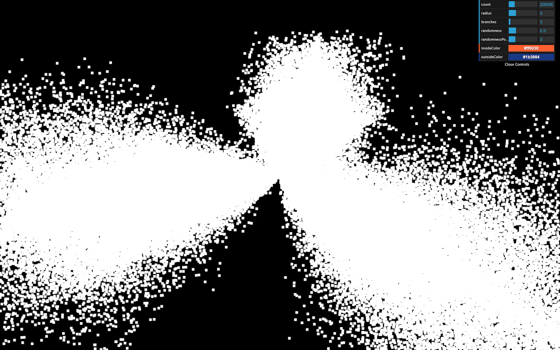
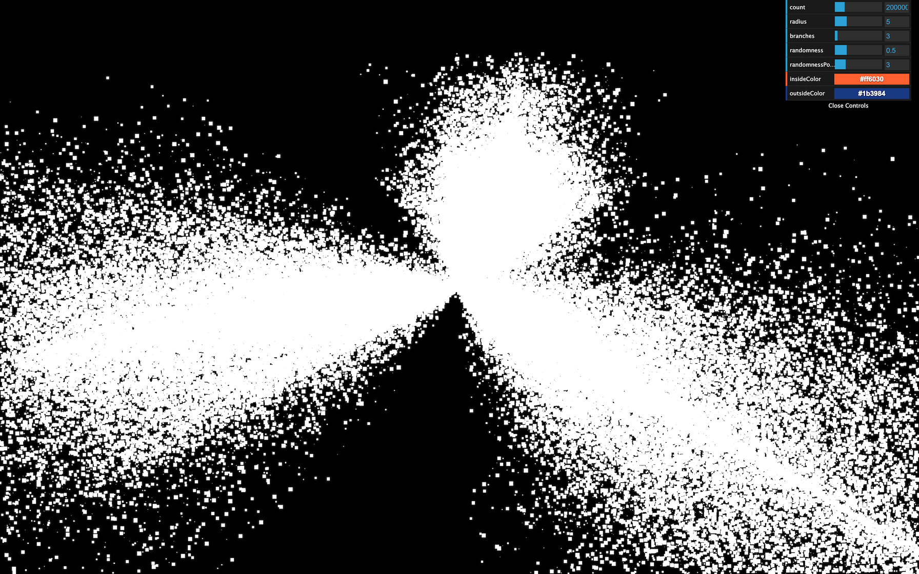
Drawing our particle pattern
It’s time to draw a better-looking particle. Just like in the Shader Patterns lesson, we first need the UV coordinates. Sadly, we cannot send the UV from the vertex shader to the fragment shader. Remember that the vertex shader controls each particle position and a square plane facing the camera appears in place of the vertex.
The good news is that we already have access to the UV in the fragment shader with gl_PointCoord . This variable is specific to the particles.
Add it to the fragment shader to see the result:
void main()
{
    gl_FragColor = vec4(gl_PointCoord, 1.0, 1.0);
}
GLSL
Copy
You should see the usual UV pattern on each particle.
Now would be a good time for you to try to draw some star shapes. You can start with a disc, then a point light and why not a star shape in the cartoons or anything you want. Keep in mind that it takes practice to be able to do that and your first attempts might not get the work done but still, you’ll gain experience.
Disc pattern
To get a disc:
- Get the distance between
gl_PointCoordand the center (vec2(0.5)). - Apply a step function to get
0.0if the distance is below0.5, and1.0if the distance is above0.5. - Invert the value.
Then, we use the strength for r , g , and b :
void main()
{
    // Disc
    float strength = distance(gl_PointCoord, vec2(0.5));
    strength = step(0.5, strength);
    strength = 1.0 - strength;

    gl_FragColor = vec4(vec3(strength), 1.0);
}
GLSL
Copy
Diffuse point pattern
To get a diffuse point:
- Get the distance between
gl_PointCoordand the center (vec2(0.5)). - Multiply it by
2.0, so it reaches1.0before touching the edge. - Invert the value.
void main()
{
    // Diffuse point
    float strength = distance(gl_PointCoord, vec2(0.5));
    strength *= 2.0;
    strength = 1.0 - strength;

    gl_FragColor = vec4(vec3(strength), 1.0);
}
GLSL
Copy
That’s better, but it still lacks realism. What we are missing here is a very intense center that dims fast.
Light point pattern
To get a light point:
- Get the distance between
gl_PointCoordand the center (vec2(0.5)). - Invert the value.
- Apply a power on it with a high number.
void main()
{
    // Light point
    float strength = distance(gl_PointCoord, vec2(0.5));
    strength = 1.0 - strength;
    strength = pow(strength, 10.0);

    gl_FragColor = vec4(vec3(strength), 1.0);
}
GLSL
Copy

The good thing with that solution is that we can control how condensed the glow is with the pow() value.
We will stick with that pattern. Because the lights look smaller, let’s increase the uSize a little:
material = new THREE.ShaderMaterial({

    // ...

    uniforms:
    {
        uSize: { value: 30 * renderer.getPixelRatio() }
    },

    // ...
})
JavaScript
Copy

Unfortunately, we are reaching performance limits for some computers, and you might experience frame rate drops. If so, reduce the number of particles or their size.
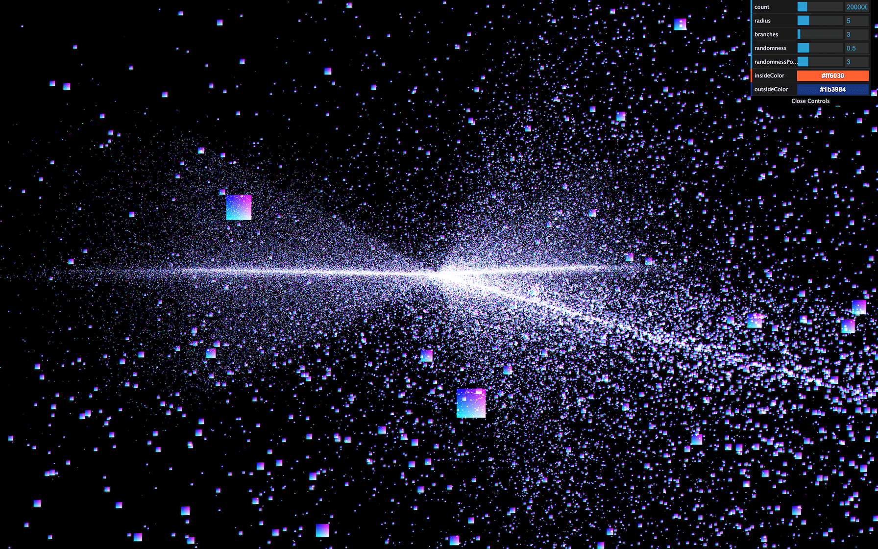
Handling the color
In the process, we lost the colors. The good news is that our shader partially supports these colors. We merely need to use their values.
To retrieve the color attribute, we should have written something like this in the vertex shader:
attribute vec3 color;
GLSL
Copy
Because we are using a ShaderMaterial and not a RawShaderMaterial there’s no need to. The code will be prepended once the shader is compiled. All we need to do is send it to the fragment shader. To do that, we are going to use a varying named vColor and update that varying with the color attribute:
// ...

varying vec3 vColor;

void main()
{
    // ...

    /**
     * Color
     */
    vColor = color;
}
GLSL
Copy
We can then retrieve it in the fragment shader with the same varying declaration and use it in a mix(...) between black and vColor according to the strength :
varying vec3 vColor;

void main()
{
    // Light point
    float strength = distance(gl_PointCoord, vec2(0.5));
    strength = 1.0 - strength;
    strength = pow(strength, 10.0);

    // Final color
    vec3 color = mix(vec3(0.0), vColor, strength);
    gl_FragColor = vec4(color, 1.0);
}
GLSL
Copy
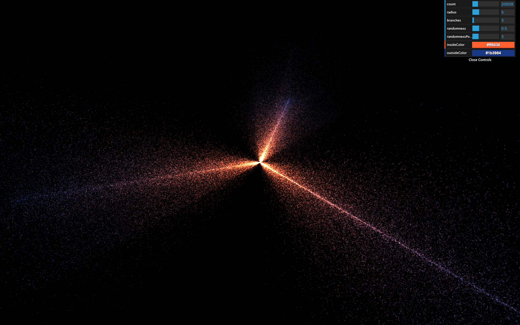
Now you see the original colors.
Animate
It’s time to animate. First, we are going to use the usual uTime uniform. Add it to the uniforms and update its value in the tick function:
material = new THREE.ShaderMaterial({

    // ...

    uniforms:
    {
        uTime: { value: 0 },
        uSize: { value: 30 * renderer.getPixelRatio() }
    },

    // ...
})

// ...

const clock = new THREE.Clock()

const tick = () =>
{
    const elapsedTime = clock.getElapsedTime()

    // Update material
    material.uniforms.uTime.value = elapsedTime

    // ...
}
JavaScript
Copy
Then we can add uTime to our shader:
uniform float uTime;
GLSL
Copy
The animation will be very average. We will make the stars rotate, but the closer to the center, the faster the rotation.
The following codes happen right after the modelPosition declaration in the vertex shader. As a reminder, the modelPosition is the position of the vertex after applying the position , rotation , and scale of the mesh. We must now update that variable.
Here’s the process:
- We calculate the particle angle —seen from above the galaxy— and its distance to the center.
- We increase that angle using the distance from the center and the
uTime. The furthest from the center the slower. - We update the position according to that new angle.
We are going to use some trigonometry.
The rotation only occurs on the x and z axes and we can let the y value as it is, which greatly simplifies the whole thing.
First, retrieve the angle using atan(...) :
vec4 modelPosition = modelMatrix * vec4(position, 1.0);

// Rotate
float angle = atan(modelPosition.x, modelPosition.z);
GLSL
Copy
atan stands for arc-tangent and you can find more about it here: https://thebookofshaders.com/glossary/?search=atan
Then, fetch the distance from the center using length() which is simple the length of the vector:
vec4 modelPosition = modelMatrix * vec4(position, 1.0);

// Rotate
float angle = atan(modelPosition.x, modelPosition.z);
float distanceToCenter = length(modelPosition.xz);
GLSL
Copy
Then, we calculate an offset angle. As we said earlier, the closer to the center, the higher the angle. We also multiply that value by uTime itself multiplied by 0.2 to slow the effect down:
vec4 modelPosition = modelMatrix * vec4(position, 1.0);

// Rotate
float angle = atan(modelPosition.x, modelPosition.z);
float distanceToCenter = length(modelPosition.xz);
float angleOffset = (1.0 / distanceToCenter) * uTime * 0.2;
GLSL
Copy
We then apply that angleOffset to the base angle :
vec4 modelPosition = modelMatrix * vec4(position, 1.0);

// Rotate
float angle = atan(modelPosition.x, modelPosition.z);
float distanceToCenter = length(modelPosition.xz);
float angleOffset = (1.0 / distanceToCenter) * uTime * 0.2;
angle += angleOffset;
GLSL
Copy
Finally, we update the modelPosition on the x and z axes with cos(...) and sin(...) :
vec4 modelPosition = modelMatrix * vec4(position, 1.0);

// Rotate
float angle = atan(modelPosition.x, modelPosition.z);
float distanceToCenter = length(modelPosition.xz);
float angleOffset = (1.0 / distanceToCenter) * uTime * 0.2;
angle += angleOffset;
modelPosition.x = cos(angle);
modelPosition.z = sin(angle);
GLSL
Copy
While this looks great, it’s not the intended result. cos(...) and sin(...) return a position on a circle of radius 1 . That is why all the particles seem the rotate on a cylinder.
To fix it, we can simply multiply the cos(...) and sin(...) by the initial radius of the vertex, which we already have in distanceToCenter :
vec4 modelPosition = modelMatrix * vec4(position, 1.0);

// Rotate
float angle = atan(modelPosition.x, modelPosition.z);
float distanceToCenter = length(modelPosition.xz);
float angleOffset = (1.0 / distanceToCenter) * uTime * 0.2;
angle += angleOffset;
modelPosition.x = cos(angle) * distanceToCenter;
modelPosition.z = sin(angle) * distanceToCenter;
GLSL
Copy
All the vertices should rotate beautifully.
Fix the randomness
If you wait for a little, you’ll see that the stars seem to create a ribbon shape. It’s like if the randomness doesn’t work anymore on the x and z axes. That is due to the rotation formula that stretches the stars on a spin pattern.
To fix that, we can remove the randomness from the position attribute, save it in a new attribute named aRandomness . Then apply this randomness after rotating the stars in the vertex shader.
Create the attribute and store the randomness in it. Don’t forget to remove the randomness from the positions :
geometry = new THREE.BufferGeometry()

const positions = new Float32Array(parameters.count * 3)
const randomness = new Float32Array(parameters.count * 3)

// ...

for(let i = 0; i < parameters.count; i++)
{
    // ...

    positions[i3    ] = Math.cos(branchAngle) * radius
    positions[i3 + 1] = 0
    positions[i3 + 2] = Math.sin(branchAngle) * radius

    randomness[i3    ] = randomX
    randomness[i3 + 1] = randomY
    randomness[i3 + 2] = randomZ

    // ...
}

geometry.setAttribute('position', new THREE.BufferAttribute(positions, 3))
geometry.setAttribute('aRandomness', new THREE.BufferAttribute(randomness, 3))

// ...
JavaScript
Copy
In the vertex shader, retrieve the attribute and apply it on the xyz of the modelPosition after applying the rotation:
// ...

attribute vec3 aRandomness;
attribute float aScale;

 // ...

void main()
{
    /**
     * Position
     */
    vec4 modelPosition = modelMatrix * vec4(position, 1.0);

    // Rotate
    float angle = atan(modelPosition.x, modelPosition.z);
    float distanceToCenter = length(modelPosition.xz);
    float angleOffset = (1.0 / distanceToCenter) * uTime * 0.2;
    angle += angleOffset;
    modelPosition.x = cos(angle) * distanceToCenter;
    modelPosition.z = sin(angle) * distanceToCenter;

    // Randomness
    modelPosition.xyz += aRandomness;

    // ...
}
GLSL
Copy
The result should look much better and the ribbon shape should be gone.
Reduce the randomness parameter for a better result:
parameters.randomness = 0.2
JavaScript
Copy
Go further
You could also add the uSize uniform to the debug panel.
After a few minutes, we cannot fully distinguish the galaxy branches. You could add a reset button or slow down the speed.
Galaxies usually have a massive black hole in their center. Why not try to create one?
28 Modified materials
Difficulty Very hard
Introduction
Until now, we were creating brand new shader materials. But what if we only want to modify one of the Three.js built-in materials? Maybe we are happy with the result of the MeshStandardMaterial, but we want to add vertex animations to it. If we were to rewrite the whole MeshStandardMaterial, it would take too much time to handle the lights, the environment maps, physically based rendering, all the types of textures, etc.
Instead, we will start from the MeshStandardMaterial and try to integrate our code in its shaders.
There are two ways of doing it:
- By using a Three.js hook triggered before the shader is compiled that let us play with the shaders and inject our code.
- By recreating the material as a brand new one, but following what is done in Three.js code and then using the same parameters, plus the ones that we want to add.
While the second option is perfectly acceptable, we would need to spend a lot of time in the Three.js source code to understand how to set everything right.
Instead, we will use the first technique. We still will spend some time in the Three.js code, but it will be much easier.
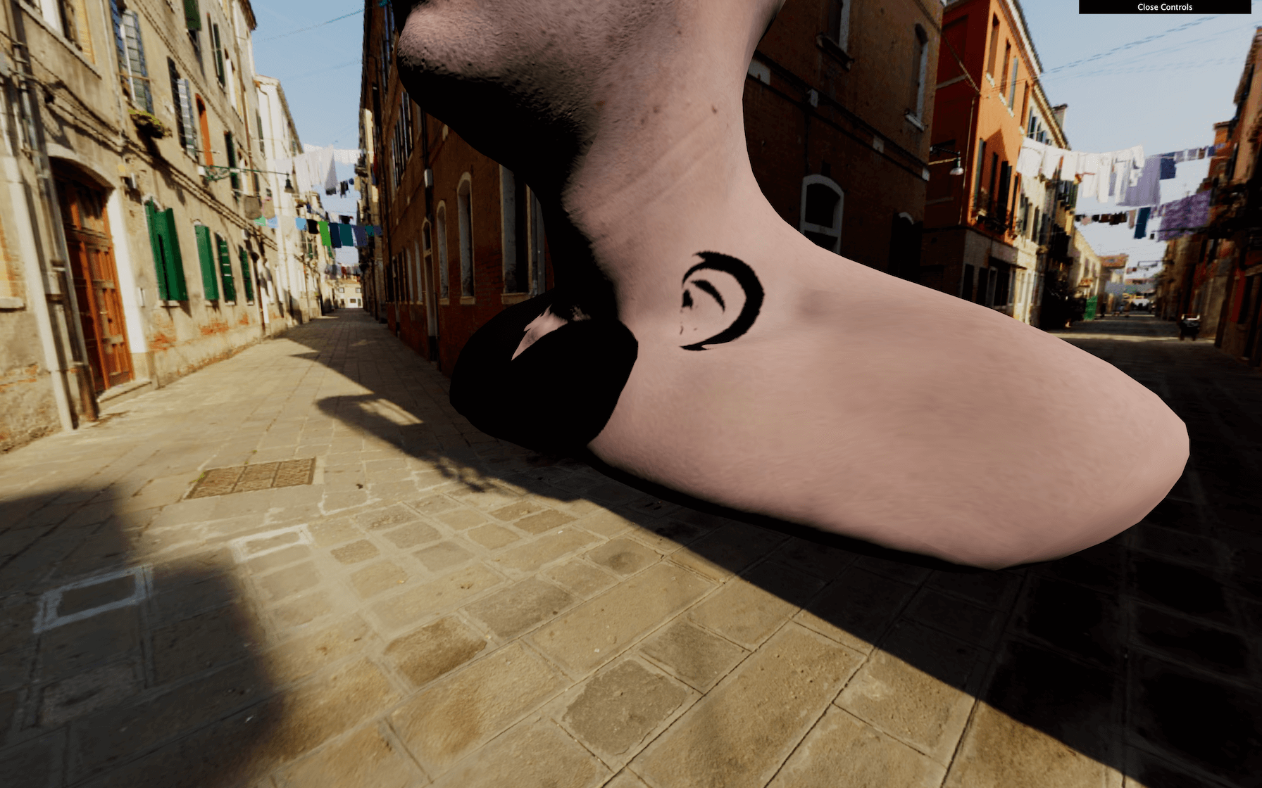
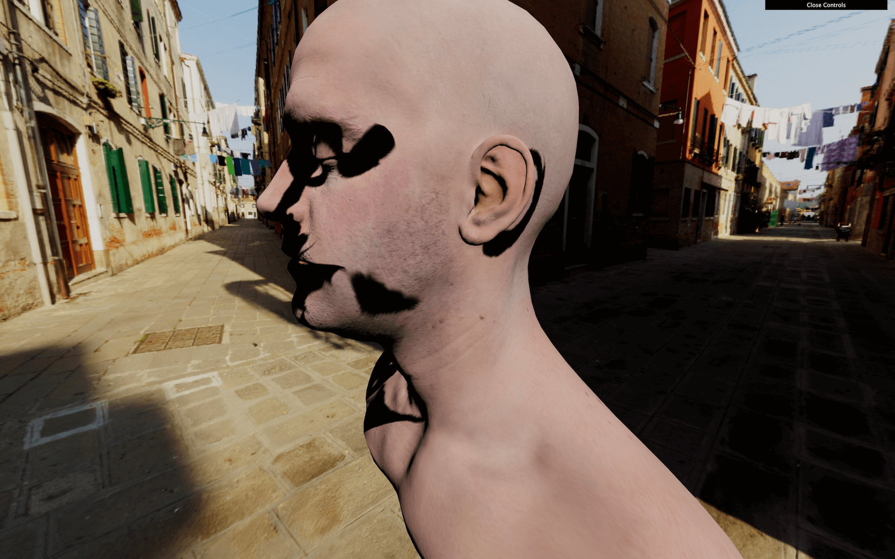
In this lesson, we will make the model vertices twist in a funny way but with all the base features of the material still working like shadows, texture, normal map, etc.
Setup
We will use the same setup as the Realistic Model Render lesson but with the famous Lee Perry-Smith head model. It’s just a popular model with only one mesh and realistic textures that should go well with our twist animation.

Both the loading and base material setup is already done. A MeshStandardMaterial with a map and a normalMap are created before loading the model. This material is then used on the only Mesh of the model. This Mesh is finally added to the scene.
Most of the following code will concern the material.
Hooking the material
We have our MeshStandardMaterial, but we want to modify its shader.
To modify a material, we first need access to its original shaders. To do that, we can use the onBeforeCompile property on the material.
If we assign a function to it, this function will be called with the shader options as the first parameter right before being compiled:
material.onBeforeCompile = (shader) =>
{
    console.log(shader)
}
JavaScript
Copy
We now have access to the vertexShader , the fragmentShader , and the uniforms and we can modify these and see the result.
Adding content to the vertex shader
If you look at the vertexShader , there isn’t much code. Three.js uses its own system to include shader parts to prevent repeating the same code between the different materials. Each #include ... will inject a code located in specific folder of the Three.js dependency.
That is, in a way, suitable for us because we can replace those parts with a simple native JavaScript replace(…).
The problem is that we don’t know which part is doing what and which one to replace. To understand the code, we need to dive into the three dependency.
Go to the /node_modules/three/src/renderers/shaders/ folder. That is where you’ll find most of the Three.js shader codes.
All the included parts are called chunks, and you can find them in the ShaderChunk/ folder.
If we look at the different chunks, it seems that begin_vertex is handling the position first by creating a variable named transformed .
Let’s build our code on that. First, we need to replace this part of the code. Because the chunk is named begin_vertex , we need to replace #include <begin_vertex> :
material.onBeforeCompile = (shader) =>
{
    shader.vertexShader = shader.vertexShader.replace('#include <begin_vertex>', '')
}
JavaScript
Copy
That should break the material because we are replacing the previous code with nothing. Our code will be a few lines long, so we are going to use back quotes.
Put the include ... back, to begin with, and not break anything:
material.onBeforeCompile = (shader) =>
{
    shader.vertexShader = shader.vertexShader.replace(
        '#include <begin_vertex>',
        `
            #include <begin_vertex>
        `
    )
}
JavaScript
Copy
This code is useless because we are replacing something with the same thing, but now we can add our own code after the include .
As an example, let’s move our head on the y axis. We saw in the /node_modules/three/src/renderers/shaders/ShaderChunks/begin_vertex.glsl.js file that a transformed variable is created and should contain the position of the vertex. It’s y property to move all the vertices:
shader.vertexShader = shader.vertexShader.replace(
    '#include <begin_vertex>',
    `
        #include <begin_vertex>

        transformed.y += 3.0;
    `
)
JavaScript
Copy
As you can see, it’s working, but the shadow seems bugged. We will fix that later.
Remove the transformed.y += 3.0; .
Twisting
Let’s do the twist… on our vertices. There are multiple mathematics ways of doing the twist effect and this time, we are going to create a matrix.
Only the GLSL part will be present in the following code.
First, we will try to rotate all the vertices at the same angle. Then we will offset that angle depending on the elevation of the vertex and animate it.
Create an angle variable with any value:
#include <begin_vertex>

float angle = 0.3;
GLSL
Copy
Even if we aren’t moving the vertices yet, you can still refresh to see if an error occurred.
If you remember, matrices are like a pipe where you send data —like a vector. The pipe will apply a transformation on that vector and output the result. We can create a matrix that scales the vector, one that rotates, one that moves, and we can even combine them. Those matrices can handle 2D transformations, 3D transformations, and even more.
In our case, we want to do a 2D transformations. Indeed, our vertices have 3D coordinates, but to do the twist animation, we are just rotating the vertices on the x and z axes, not up and down on the y axis.
To create the 2D rotation matrix, we won’t go into mathematic details. Instead, we’ll use this function that returns a 2 dimensions matrix ( mat2 ):
mat2 get2dRotateMatrix(float _angle)
{
    return mat2(cos(_angle), - sin(_angle), sin(_angle), cos(_angle));
}
GLSL
Copy
If you want to know more about it, you can find details on The Book of Shaders: https://thebookofshaders.com/08/
But where should we add this function exactly? If it were our own shader, we would have put it before the main function, and this is exactly what we are going to do. One chunk outside of the main function is common . This chunk has the advantage of being present on all shaders. Let’s replace this part as we did with the begin_vertex chunk:
material.onBeforeCompile = (shader) =>
{
    shader.vertexShader = shader.vertexShader.replace(
        '#include <common>',
        `
            #include <common>
        `
    )

    // ...
}
JavaScript
Copy
We can now add our get2dRotateMatrix :
material.onBeforeCompile = (shader) =>
{
    shader.vertexShader = shader.vertexShader.replace(
        '#include <common>',
        `
            #include <common>

            mat2 get2dRotateMatrix(float _angle)
            {
                return mat2(cos(_angle), - sin(_angle), sin(_angle), cos(_angle));
            }
        `
    )

    // ...
}
JavaScript
Copy
Nothing changed, but we now have access to the get2dRotateMatrix anywhere in the shader, as in the begin_vertex chunk. That is because all the chunks are merged as if it was only one code.
Create the rotateMatrix variable using the get2dRotateMatrix function:
#include <begin_vertex>

float angle = 0.3;
mat2 rotateMatrix = get2dRotateMatrix(angle);
GLSL
Copy
We now have access to a matrix named rotateMatrix that should rotate a vec2 . Let’s apply this matrix to the x and z properties together:
#include <begin_vertex>

float angle = 0.3;
mat2 rotateMatrix = get2dRotateMatrix(angle);

transformed.xz = rotateMatrix * transformed.xz;
GLSL
Copy
The head should have rotate. Again, don’t mind the shadows; we will handle that later.
We almost have our twist rotation. We only need to vary the angle according to the elevation:
float angle = position.y * 0.9;
GLSL
Copy
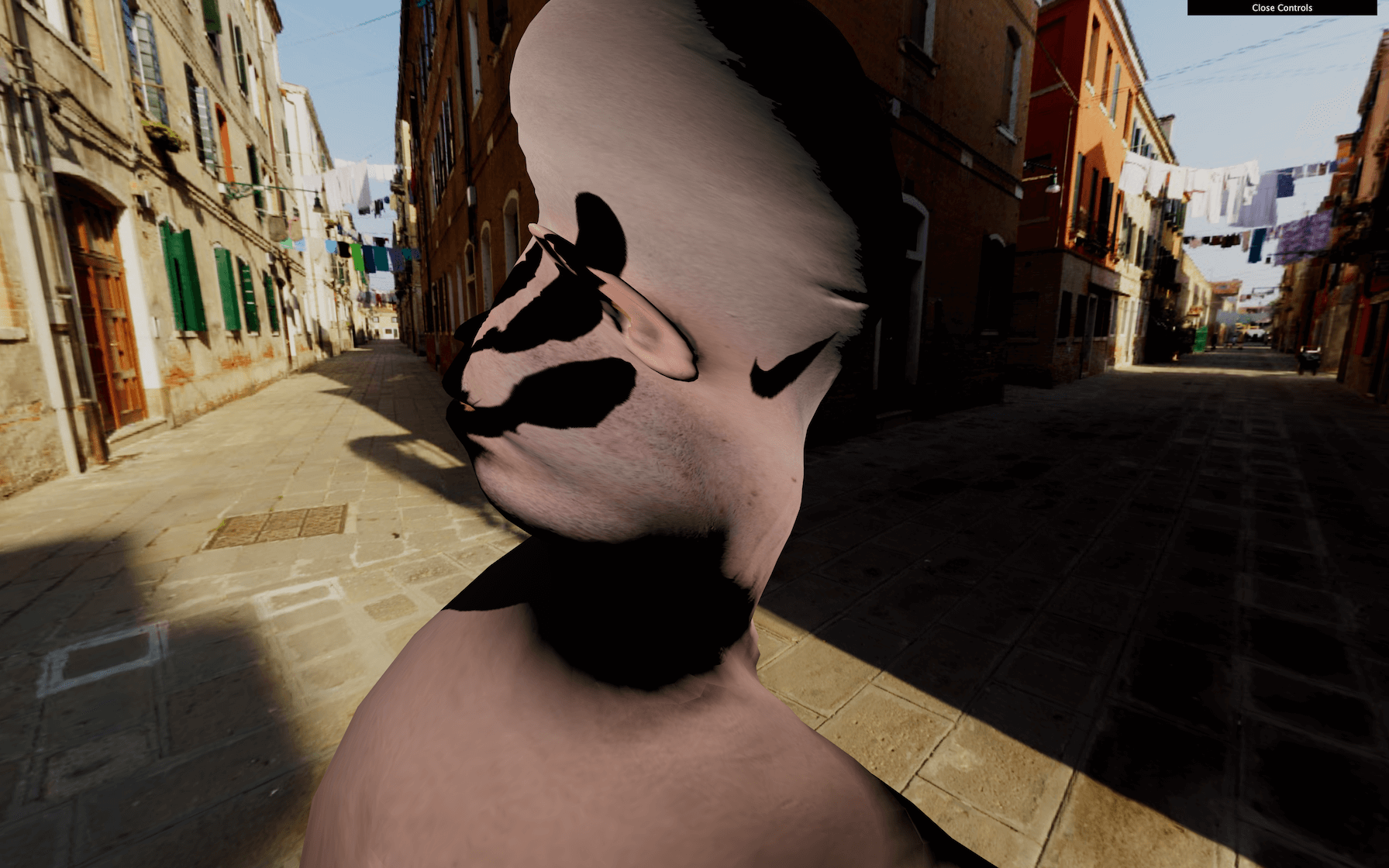
Poor head. It’s time to animate the angle.
Animating
We will use the same technique as before, and send a uTime uniform to our shader. We already have access to the uniforms with shader.uniforms . Let’s update it the same way we update a ShaderMaterial:
material.onBeforeCompile = function(shader)
{
    shader.uniforms.uTime = { value: 0 }

    // ...
}
JavaScript
Copy
We can now retrieve our uTime uniform in the common chunk:
#include <common>

uniform float uTime;

mat2 get2dRotateMatrix(float _angle)
{
    return mat2(cos(_angle), - sin(_angle), sin(_angle), cos(_angle));
}
GLSL
Copy
And use it in the begin_vertex chunk:
#include <begin_vertex>

float angle = (position.y + uTime) * 0.9;
mat2 rotateMatrix = get2dRotateMatrix(angle);

transformed.xz = rotateMatrix * transformed.xz;
GLSL
Copy
You should get the same result because we aren’t animating the uTime value. Unluckily, we have a JavaScript problem. We have no apparent way to access the uniform in the tick function. Unlike a ShaderMaterial, we cannot just access the uniforms of material , and this is due to the Three.js structure.
There are many ways of fixing that. All we need is access to those uniforms. Let’s create a customUniforms object before the material and add our uTime inside:
const customUniforms = {
    uTime: { value: 0 }
}
GLSL
Copy
Then, we use that object in the onBeforeCompile function:
material.onBeforeCompile = (shader) =>
{
    shader.uniforms.uTime = customUniforms.uTime

    // ...
}
JavaScript
Copy
And because our customUniforms has been declared outside of any scope, we can simply update it in the tick function with the elapsedTime variable:
const clock = new THREE.Clock()

const tick = () =>
{
    const elapsedTime = clock.getElapsedTime()

    // Update material
    customUniforms.uTime.value = elapsedTime

    // ...
}
JavaScript
Copy
Now, the head is rotating.
Let’s fix the shadows.
Fixing the shadow
As we saw in previous lessons, when using shadows, Three.js makes renders for the scene from the light point of view. Those renders result in pictures of what is in the shadow or the light. When those renders occur, all the materials are replaced by another set of materials dedicated to that specific render. The problem is that this kind of material doesn’t twist because it has nothing to do with our modified MeshStandardMaterial.
We can see that if we add a plane right behind the head:
/**
 * Plane
 */
const plane = new THREE.Mesh(
    new THREE.PlaneBufferGeometry(15, 15, 15),
    new THREE.MeshStandardMaterial()
)
plane.rotation.y = Math.PI
plane.position.y = - 5
plane.position.z = 5
scene.add(plane)
JavaScript
Copy
We need to find a way to twist that material too.
The material used for the shadows is a MeshDepthMaterial and we cannot access that material easily, but we can override it with the property customDepthMaterial on the mesh in order to tell Three.js to use a custom material.
First, let’s create a this custom material. We are going to use a MeshDepthMaterial because this is exactly what Three.js is using during those renders. We will call it depthMaterial and add THREE.RGBADepthPacking to its depthPacking property:
const depthMaterial = new THREE.MeshDepthMaterial({
    depthPacking: THREE.RGBADepthPacking
})
JavaScript
Copy
We won’t explain what the depthPacking is in detail here, but it’s just a better way of storing the depth by using the r , g , b , and a separately for better precision and Three.js needs it.
To apply our custom depth material, when our model is loaded, we change the customDepthMaterial property with our own depthMaterial :
gltfLoader.load(
    '/models/LeePerrySmith/LeePerrySmith.glb',
    (gltf) =>
    {
        // ...

        mesh.material = material // Update the material
        mesh.customDepthMaterial = depthMaterial // Update the depth material

        // ...
    }
)
JavaScript
Copy
Here, we did it on the only mesh in the model but if we had a more complex model with multiple meshes, we would have to traverse it and update all the materials.
We can now apply all the changes to the shader we’ve made before but for the depthMaterial .
Copy and paste the onBeforeCompile part:
depthMaterial.onBeforeCompile = (shader) =>
{
    shader.uniforms.uTime = customUniforms.uTime
    shader.vertexShader = shader.vertexShader.replace(
        '#include <common>',
        `
            #include <common>

            uniform float uTime;

            mat2 get2dRotateMatrix(float _angle)
            {
                return mat2(cos(_angle), - sin(_angle), sin(_angle), cos(_angle));
            }
        `
    )
    shader.vertexShader = shader.vertexShader.replace(
        '#include <begin_vertex>',
        `
            #include <begin_vertex>

            float angle = (position.y + uTime) * 0.9;
            mat2 rotateMatrix = get2dRotateMatrix(angle);

            transformed.xz = rotateMatrix * transformed.xz;
        `
    )
}
JavaScript
Copy
If you look at the shadow on the plane, you should see the twist too. But still, we have a problem. The drop shadow is fine, but the core shadow on the model seems wrong and it looks like the shadow is rotating with the vertices.
This is an issue related to the normals .
Fixing the normals
In the previous lessons, we saw that normals are coordinates associated with each vertices that tell what direction the faces are facing. If we were to see those normals, they would be arrows all over the model pointing on the outside. Those normals are used for things like lighting, reflecting and shadowing.
When we rotated our vertices, we merely rotated the positions, but we didn’t rotate the normals. We need to modify the chunk that handles normals.
Hang on; this part is a little tricky.
The chunk handling the normals first is called beginnormal_vertex . Let’s replace it for the material —not the depthMaterial because this one doesn’t need the normals:
material.onBeforeCompile = (shader) =>
{
    // ...

    shader.vertexShader = shader.vertexShader.replace(
        '#include <beginnormal_vertex>',
        `
            #include <beginnormal_vertex>
        `
    )

    // ...
}
JavaScript
Copy
If you look at the chunk located in /node_modules/three/src/renderers/shaders/ShaderChunks/beginnormal_vertex.glsl.js , you’ll see that the normal variable name is objectNormal . We could be tempted to do the same thing we did for the transformed variable:
#include <beginnormal_vertex>

float angle = (position.y + 4.0) * sin(uTime) * 0.9;
mat2 rotateMatrix = get2dRotateMatrix(angle);

objectNormal.xz = objectNormal.xz * rotateMatrix;
GLSL
Copy
Unfortunately, this will result in a shader error, containing the following messages: 'angle' : redefinition and 'rotateMatrix' : redefinition .
That happens because we forgot that all those shaders chunks, in the end, will be merged into a unique shader. The code we added to the beginnormal_vertex chunk will be aside of the code added to the begin_vertex , and we cannot have two variable declarations with the same name.
We need to remove the double declarations. If you look at the initial vertexShader , you’ll see that the beginnormal_vertex happens before the begin_vertex . This means that we should remove the angle and rotateMatrix from the begin_vertex :
material.onBeforeCompile = function(shader)
{
    // ...

    shader.vertexShader = shader.vertexShader.replace(
        '#include <beginnormal_vertex>',
        `
            #include <beginnormal_vertex>

            float angle = (position.y + uTime) * 0.9;
            mat2 rotateMatrix = get2dRotateMatrix(angle);

            objectNormal.xz = objectNormal.xz * rotateMatrix;
        `
    )
    shader.vertexShader = shader.vertexShader.replace(
        '#include <begin_vertex>',
        `
            #include <begin_vertex>

            transformed.xz = rotateMatrix * transformed.xz;
        `
    )
}
JavaScript
Copy
Everything should be working fine now, and our begin_vertex is using the angle and rotateMatrix from the beginnormal_vertex chunk.
Go further
That concludes our lesson, but you can go even further if you want.
You could control the twist with the debug panel or even the mouse.
You could test other animations. For instance, this formula for the angle looks even more disturbing —make sure to change both the material and the depthMaterial :
float angle = (sin(position.y + uTime)) * 0.4;
GLSL
Copy
You could also improve the way we handle the GLSL codes. Having dedicated files could be handy.